1-37
UX-P3
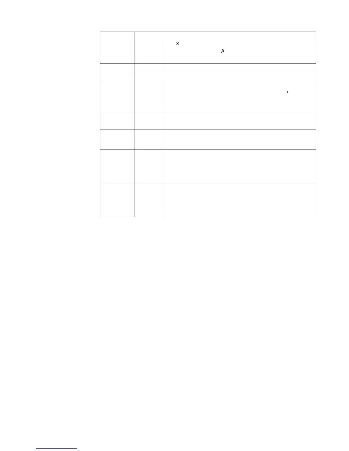
Pin name Pin No.
Descriptions
Vref
19
DI
CL
1
36
Serial data and clock input pin for control.
LINP
RINP
6
32
Non-inverted input pin of general-purpose operation amplifier.
Keep this pin open when not used.
LINM
RINM
5
33
Output pin of general-purpose operation amplifier.
Connect to L (R) INN pin when not used.
(Connect between pins 5 and 4)
(Connect between pins 33 and 34)
LOPOUT
ROPOUT
4
34
0.5 VDD voltage generation block for analog ground.
Capacitor of several 10 F to be connected between Vref and
AWSS (VSS) as a counter-measure against power ripple.
VSS
3
Ground pin
VDD
35
Supply pin
CE
2
Chip enable pin.
Data written into an internal latch in a timing of [H] [L].
Each analog switch is activated.
Data transfer enabled at [H] level.
Non-inverted input pin of general-purpose operation amplifier.
Connect to L (R) OPOUT pin when not used.
(Connect between pins 5 and 4)
(Connect between pins 33 and 34)
 Loading...


