1-14 (No.MB049)
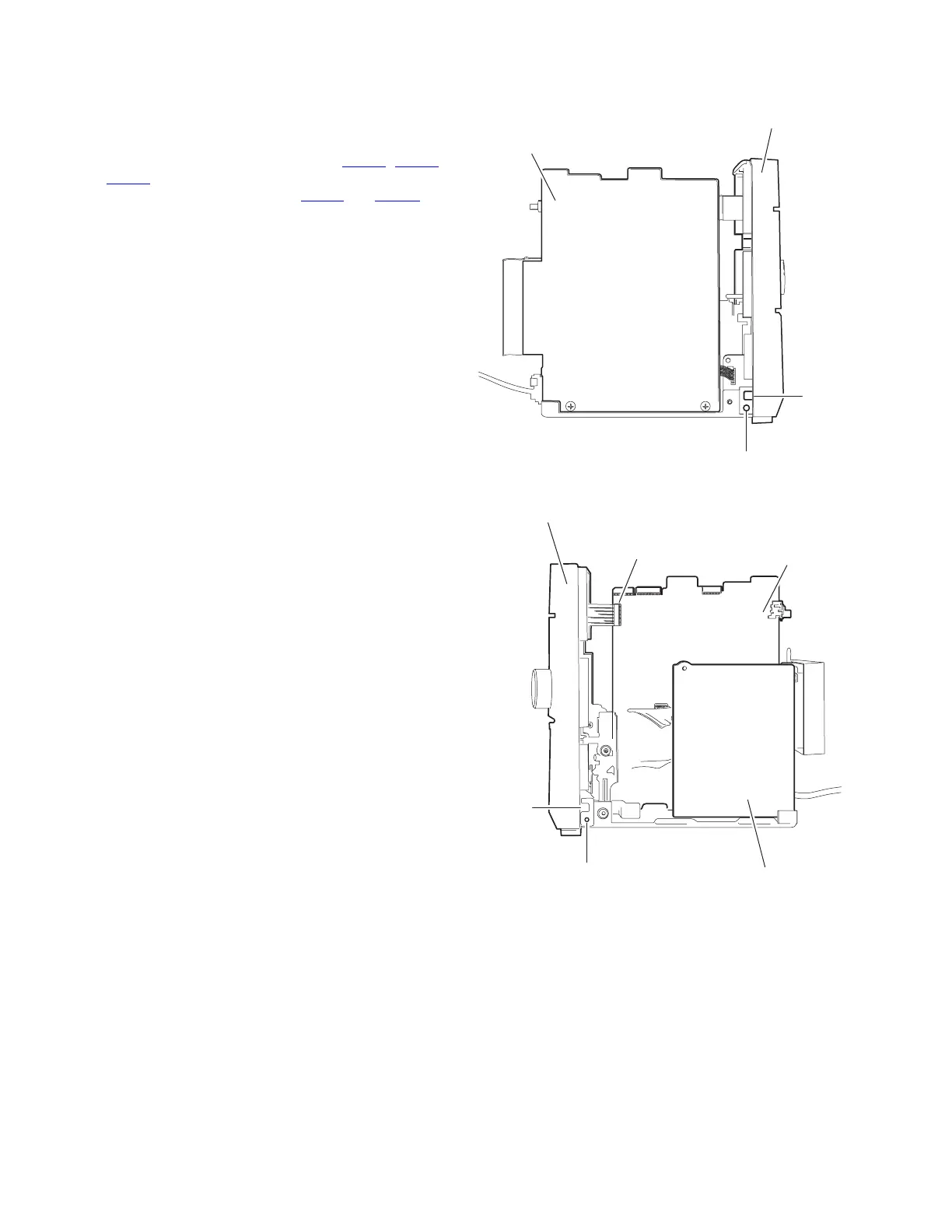
3.1.8 Removing the front panel assembly
(See Fig.11, 16 and 17)
• Prior to performing the following procedure, remove the metal
cover, the rear cover, the CD mechanism assembly and the
rear panel.
(1) Disconnect the card wire from connector CN900
, CN901
and CN931 on the main board (Refer to Fig.11).
(2) Disconnect the wire from connector CN906 and FW903 on
the main board (Refer to Fig.11).
(3) Remove the two screws L on each lower side of the body.
(4) Release the lower joints d on each side of the body using
a screwdriver. Pull out thefront panel assembly toward the
front.
Fig.16
Fig.17
L
Joint d
Front panel assembly
Main board
L
Joint d
Front panel assembly
Power transformer
assembly
Main board
CN931
 Loading...


