(No.MB262)1-13
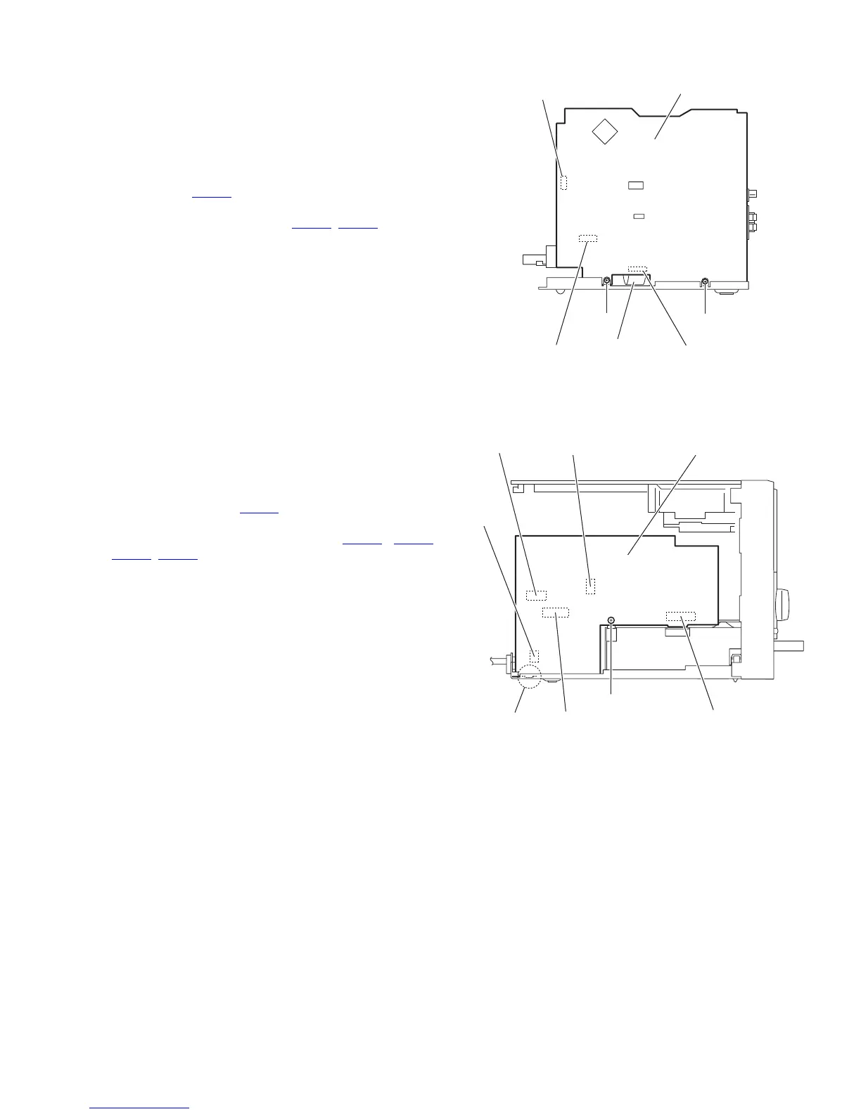
3.1.8 Removing the main board
(See Fig.16)
• Prior to performing the following procedures, remove the side
panels L/R, front panel assembly, top cover assembly, tuner
and rear panel.
(1) From the right side of the main body, remove the two
screws J attaching the main board.
(2) Remove the main board toward this side and disconnect
the connector CN200
on the main board.
(3) From the forward side of the main board, disconnect the
card wires from the connectors (CN210
, CN221).
Fig.16
3.1.9 Removing the power supply board
(See Fig.17)
• Prior to performing the following procedures, remove the side
panel L and rear panel.
(1) From the left side of the main body, remove the screw K at-
taching the power supply board.
(2) Remove the power supply board toward this side and dis-
connect the connector CN104
on the power supply board.
(3) From the forward side of the power supply board, discon-
nect the wires from the connectors (CN101
, CN102,
CN103, CN105).
Reference:
When attaching the power supply board, insert the section h of
the power supply board in the hole of the bottom chassis be-
fore attaching the screw K.
Fig.17
J
J
CN200
Card wire
CN221
Main board
CN210
Power supply board
CN103
CN102
CN101
CN105
CN104
K
h

 Loading...


