1-14 (No.MB262)
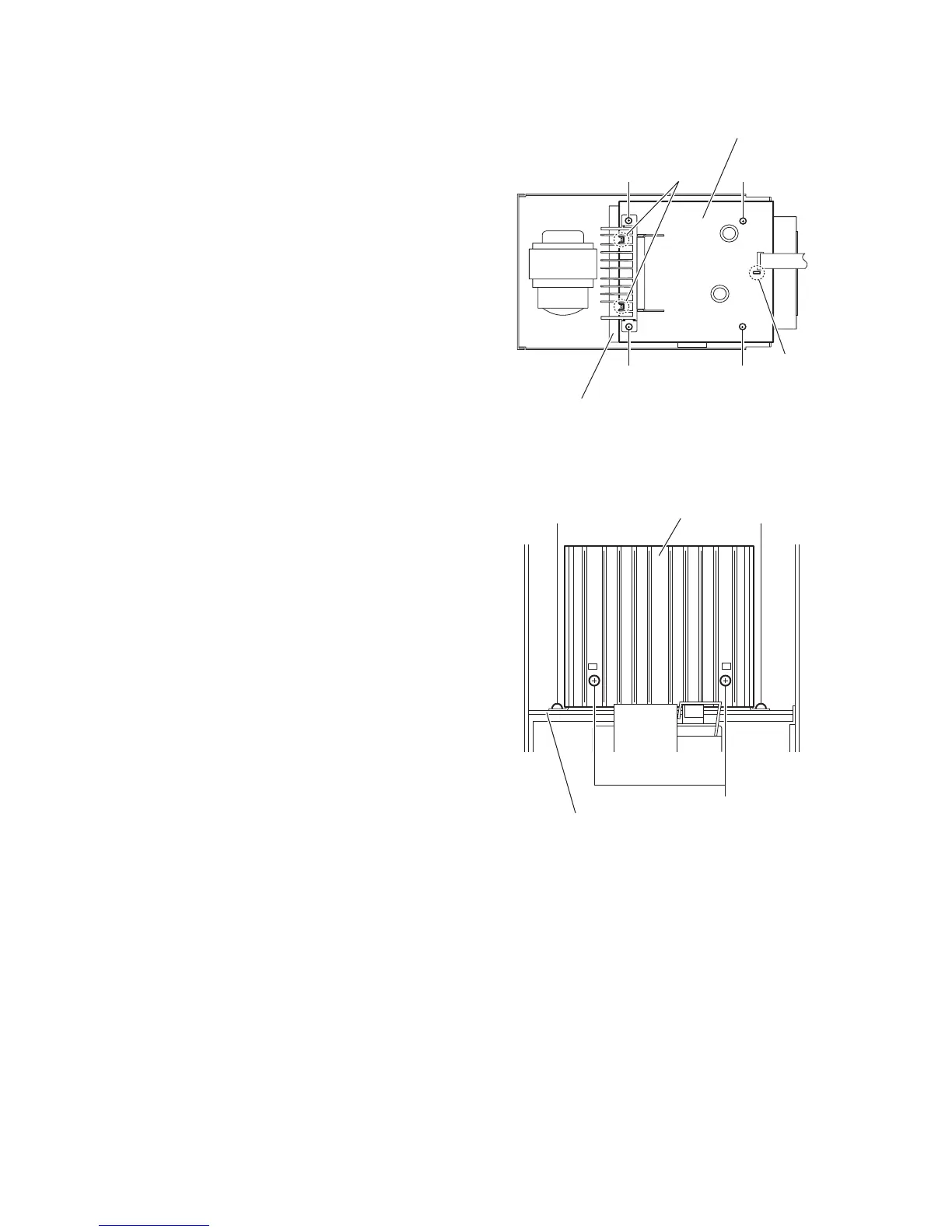
3.1.10 Removing the power amplifier board
(See Fig.18)
• Prior to performing the following procedures, remove the side
panels L/R, front panel assembly, top cover assembly, tuner,
rear panel, main board and power supply board.
(1) From the top side of the main body, remove the four screws
L attaching the power amplifier board.
(2) Lift the power amplifier board and remove it from the en-
gagement sections (i, j) of the shield case.
Fig.18
3.1.11 Removing the heat sink
(See Fig.19.)
• Prior to performing the following procedure, remove the side
panels L/R, front panel assembly, top cover assembly, tuner,
rear panel, main board, power supply board and power ampli-
fier board.
(1) From the side of the power amplifier board, remove the two
screws M attaching the heat sink.
(2) From the side of the power amplifier board, remove the two
screws N attaching the heat sink.
Fig.19
Power amplifier board
L
L
LL
Shield case
j
i
Heat sink
Power amplifier board
N
M M

 Loading...


