(No.MB262)1-15
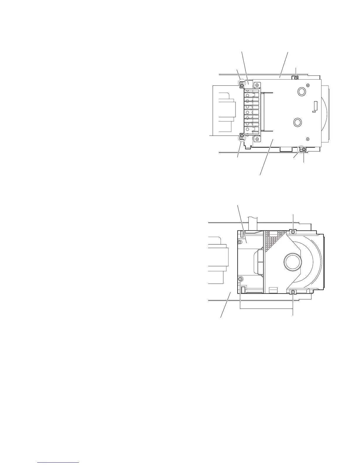
3.1.12 Removing the CD mechanism assembly
(See Figs.20 and 21)
• Prior to performing the following procedures, remove the side
panels L/R, front panel assembly, top cover assembly, tuner,
rear panel, main board and power supply board.
(1) From the top side of the main body, remove the four screws
P attaching the shield case to the bottom chassis. (See
Fig.20.)
Reference:
When attaching the shield case on the bottom chassis,
align the projections (k, m, n) of the bottom chassis in the
holes of the shield case. (See Fig.20.)
(2) Take out the shield case with the power amplifier board
from the bottom chassis.
(3) Remove the three screws Q attaching the CD mechanism
assembly to the bottom chassis. (See Fig.21.)
Fig.20
Fig.21
Bottom chassis
P
P
P
m
k
n
Shield case
Power amplifier board
CD mechanism assembly
Bottom chassis
Q
Q

 Loading...


