(No.MB262)1-9
3.1.3 Removing the top cover assembly
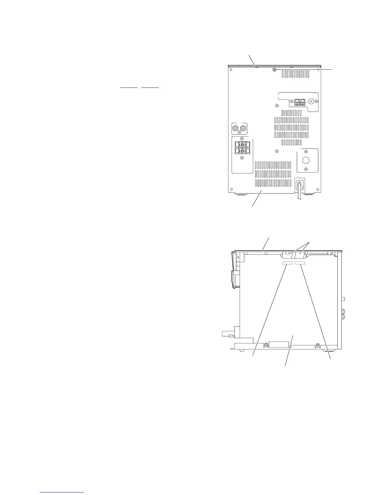
(See Figs.9 and 10)
• Prior to performing the following procedures, remove the side
panels L/R and front panel assembly.
(1) From the back side of the main body, remove the screw D
attaching the top cover assembly to the rear panel. (See
Fig.9.)
(2) From the right side of the main body, disconnect the card
wires from the connectors (CN701
, CN702) on the main
board. (See Fig.10.)
(3) Take out the top cover assembly from the main body.
Fig.9
Fig.10
Top cover assembly
D
Rear panel
Top cover assembly
Card wires
CN702
CN701
Main board

 Loading...


