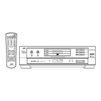
XV-M565BK/M567GD
1-17
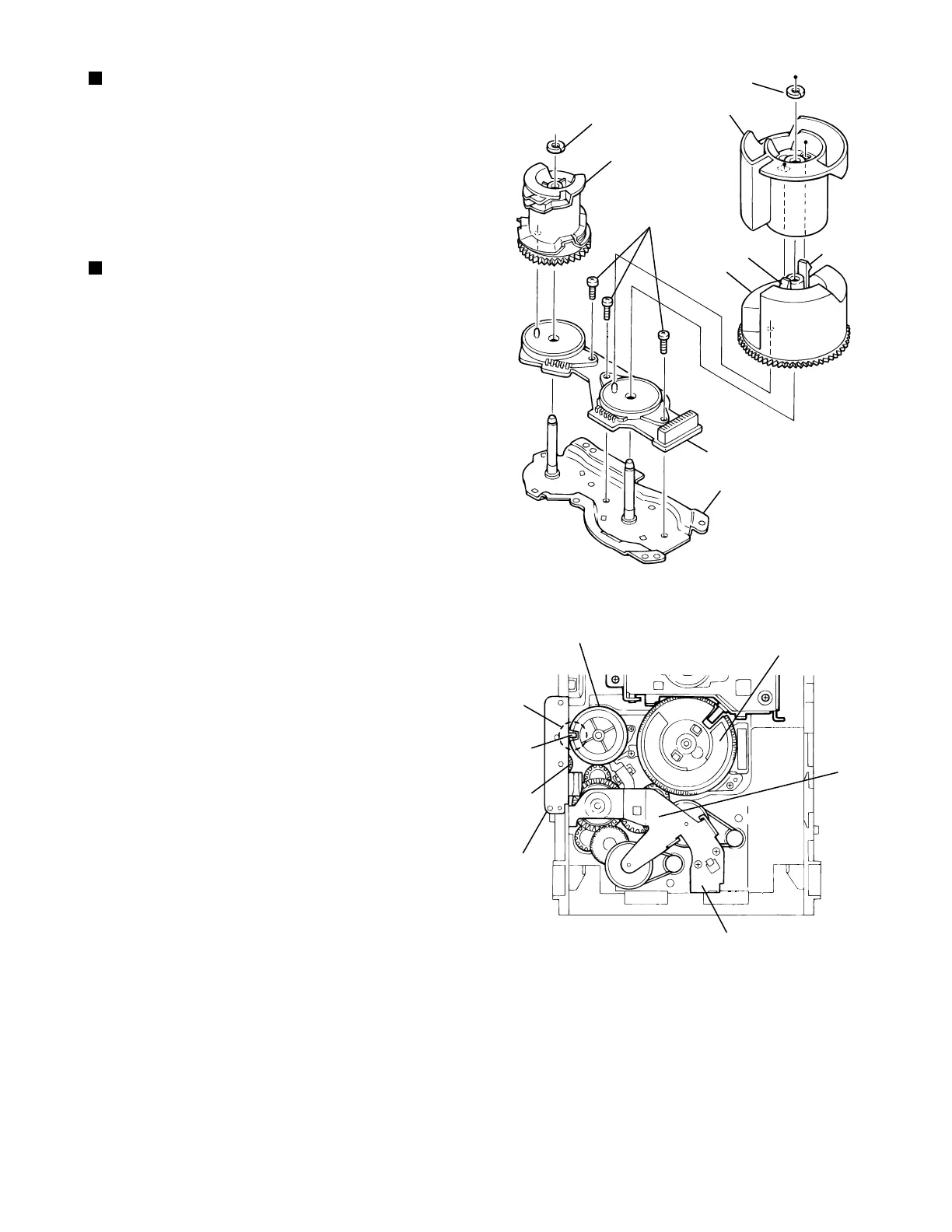
Fig.23
[Caution]
To reassemble the cylinder gear, etc.with the
cam unit (cam gear and cams
R1/R2
assembly),
gear unit and drive unit, align the position of the
pawl n on the drive unit to that of the notch on
the cam gear L. Then, make sure that the gear
unit is engaged by turning the cam gear L
(See Fig. 24).
Removing the cams R1/R2 assembly
and cam gear L (See Fig.23)
1.
2.
3.
4.
Remove the slit washer fixing the cams R1 and R2
assembly.
By removing the two pawls s fixing the cam R1,
separate R2 from R1.
Remove the slit washer fixing the cam gear L.
Pull out the cam gear L from the C.G. base assembly.
Removing the C.G. base assembly
(See Fig.23 and 24)
Remove the three screws L retaining the C.G. base
assembly.
Fig.24
L
Slit washer
Pawl
Cam R2
Slit washer
Cam gear L
Cam switch board
C.G. base assembly
Cam R1
Pawl
Cam gear L
Notch
Cylinder
gear
Gear bracket
Cam R1, R2 assembly
Gear unit
Drive unit
n
Pawl
s
s
 Loading...