XV-M565BK/M567GD
1-20
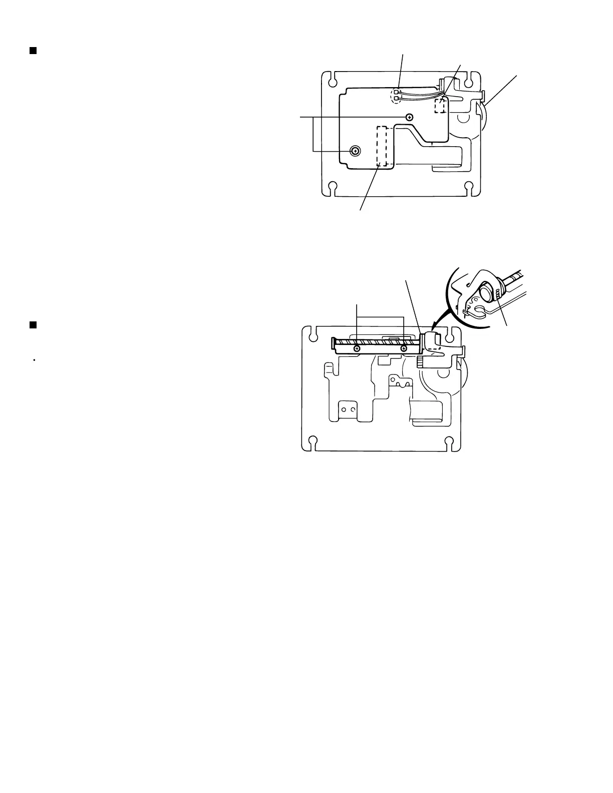
Disconnect the flexible harness from connector
CN12 and CN13 on the connection board on the
under side of the chassis.
Unsolder the two parts b (the red and black wires
extending from the spindle motor) on the connection
board.
Remove the two screws A attaching the connection
board and detach the relay board.
1.
2.
3.
Removing the connection board
(See Fig.9)
Prior to performing the following procedure, remove
the connection board.
Unsolder the flexible harness g of the feed motor.
Remove the two screws E attaching the feed motor
assembly and detach the feed motor assembly.
1.
2.
Removing the feed motor assembly
(See Fig.10)
Part b -soldering
g
CN13
CN12
Feed motor assembly
A
E
Spindle motor
Fig.9
Fig.10
 Loading...