XV-M565BK/M567GD
1-19
Unsolder the two parts b on the connection board.
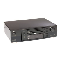
Remove the screw C attaching the sensor holder
and detach the sensor holder from the turn table
bracket. Slacken and remove the flexible harness of
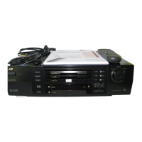
the part c as shown in Fig.6. Pull up the hook d and
remove the flexible harness from the sensor holder.
(When reattaching the sensor holder)
1.
2.
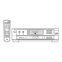
Remove the three screws D attaching the spindle
motor assembly.
Release the tab by moving the spindle motor
assembly to the tab, and remove the spindle motor
assembly.
3.
4.
Removing the Spindle Motor Assembly
(See Fig.4 to 8)
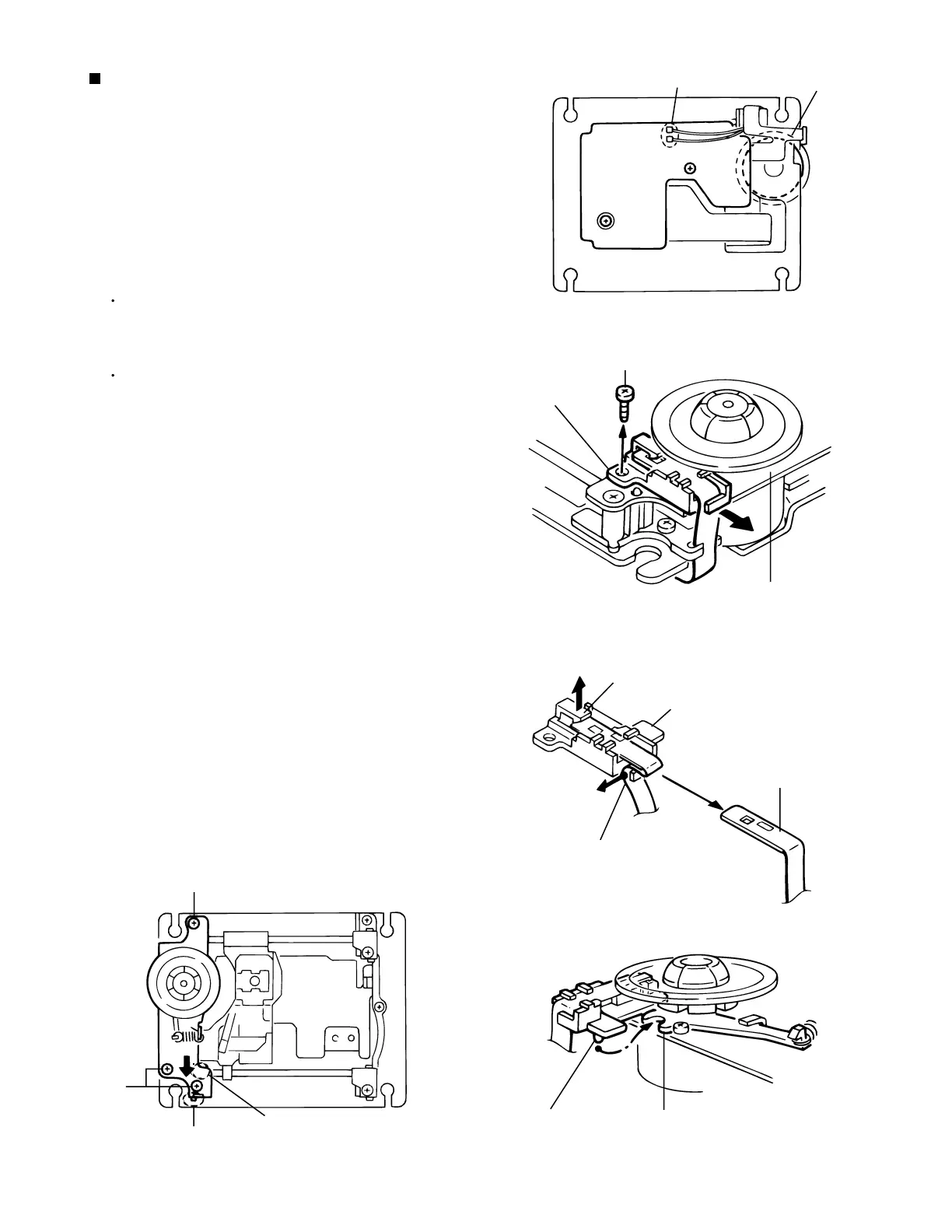
Do not lose the spring of the shaft f by
the tab.
ATTENTION:
Let the flexible harness through the part c of the
sensor holder and reattach it to the hook d
correctly (See Fig.6).
Reattach the pin e of the sensor holder to the
notch of the radial lever and reattach the sensor
holder to the turn table bracket.
*Part b - soldering
Spindle motor
C
D
D
Sensor holder
Turn table bracket
Hook d
Part c
Pin e
Radial lever
Sensor holder
f
Flexible harness
Tab
Fig.4
Fig.5
Fig.6
Fig.7Fig.8
It is not necessary to remove
at the spindle motor unit exchange.
 Loading...