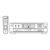
XV-M565BK/M567GD
1-56
1
2
3
4
5
6
7
8
9
10
11
12
13
14
15
16
17
18
19
20
21
22
23
24
25
26
27
28
29
30
31
32
33
34
35
36
37
38
39
40
41
42
Programmable I/O pins.Input mode after reset.
8-bit bi-derectional host data bus. writes data to the decoder Code FIFO via HDATA.
MSB of the 32-bit word is written first. The host also reads and writes the decoder
internal registers and local SDRAM via HDATA.
3.3-V supply voltage for I/O signals.
8-bit bi-derectional host data bus. writes data to the decoder Code FIFO via HDATA.
MSB of the 32-bit word is written first. The host also reads and writes the decoder
internal registers and local SDRAM via HDATA.
Ground for core logic and I/O signals.
8-bit bi-derectional host data bus. writes data to the decoder Code FIFO via HDATA.
MSB of the 32-bit word is written first. The host also reads and writes the decoder
internal registers and local SDRAM via HDATA.
2.5-V supply voltage for core logic.
Hardware reset. An external device asserts RESET(active LOW) to execute a decoder
hardware reset. To ensure proper initialization after power is stable,assert RESET for at
least 20 ms.
Ground for core logic and I/O signals.
Transfer not complate / data acknowledge. Active LOW to indicate host initiated transfer
is not complate.WAIT is asserted after the falling edge of CS and reasserted when
decoder is ready to complate transfer cycle. Open drain signal, must be pulled-up via
1kW to 3.3 volts. Driven high for 10 ns before tristate.
Host interrupt. Open drain signal, must be pulled-up via 4.7kW to 3.3 volts.
Driven high for 10 ns before tristate.
3.3-V supply voltage for I/O signals.
Connected to TP540
Ground for core logic and I/O signals.
Connected to TP541
Not used
(Programmable I/O pins. Input mode after reset)
3.3-V supply voltage for I/O signals.
Not used (Programmable I/O pins. Input mode after reset)
Ground for core logic and I/O signals.
Not used (Programmable I/O pins. Input mode after reset)
Connected to TP550
Connected to TP551
Connected to TP552
Connected to TP553
Connected to TP554
3.3-V supply voltage for I/O signals.
Connected to TP555
Ground for core logic and I/O signals.
Connected to TP556
2.5-V supply voltage for core logic.
Connected to TP557
Ground for core logic and I/O signals.
I/O
I/O
-
I/O
-
I/O
-
I
-
O
O
-
-
-
-
-
-
-
-
-
-
-
-
-
-
-
-
-
-
-
-
-
Pin No.
Symbol
TEST PIN0
H DATA 0
H DATA 1
H DATA 2
E VDD
H DATA 3
E VSS
H DATA 4
H DATA 5
H DATA 6
H DATA 7
i vdd
RST
i vss
WAIT
INT
E VDD
ARAM OE
E VSS
ARAM WE
ARAM DATA0
ARAM DATA1
ARAM DATA2
ARAM DATA3
ARAM DATA4
ARAM DATA5
E VDD
ARAM DATA6
E VSS
ARAM DATA7
ARAM ADDR0
ARAM ADDR1
ARAM ADDR2
ARAM ADDR3
ARAM ADDR4
E VDD
ARAM ADDR5
E VSS
ARAM ADDR6
i vdd
ARAM ADDR7
i vss
I/O
Function
ZIVA3-PEO (IC501) : AV Decoder
ZIVA3-PEO (1/5)
1.Pin function
 Loading...