2+
1+
2-
1-
SPEAKON OUT A
2+
1+
2-
1-
SPEAKON OUT B
19. CH 4 LINK OUT/DSP OUT SWITCH. Press the switch to use output 18 as an auxiliary XLR balanced output
controlled via the K-Framework software.
20. CH 5/6 AES/EBU INPUT. XLR input connector for two-channel AES/EBU digital audio, accepting sample
rates from 32 kHz – 96 kHz.
21. CH 5/6 AES/EBU OUTPUT. XLR output, providing two-channel digital audio from ch 5/6 AES/EBU input,
at a sample rate of 48 kHz.
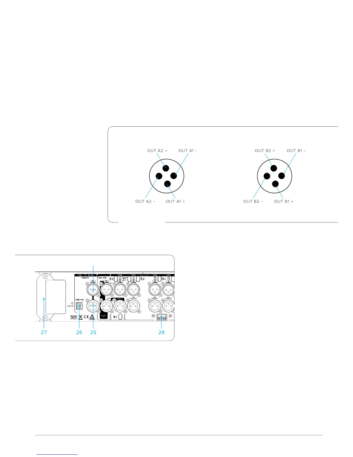
22. POWER OUT A. Speakon output to drive passive speakers. 1+/1- provides OUT A1, 2+/2- provides OUT
A2.
23. POWER OUT B. Speakon output to power passive speakers. 1+/1- provides OUT B1, 2+/2- provides OUT B2.
11.3 REMoTE CoNTRoL
CH 5 - 6
24
24. REMOTE RS485 LINK INPUT. XLR input for
connecting the amplifier from another RS485
device in a K-Framework network. RS485 Link
Input can also be used to connect a computer
running the K-Framework software (requires
K-USB USB-to-RS485 adapter).
25. REMOTE RS485 LINK OUTPUT. XLR output
for connecting additional RS485 devices in a
K-Framework network.
26. REMOTE USB Input. Connects a computer running the K-Framework software, for remote control of
the amplifier. Users can manage an entire network of RS485 devices with one PC connected via USB.
27. EXTENSION CONNECTOR. Multi-pin connector for various K-array extension modules, for wireless
control and audio transmission, memory extension, digital signal encoding and audio reproduction.
28. KA-POT1 CONNECTOR. These two analog GPIO ports allow the user to control same amplifier’s
parameters using the K-POT1 accessory. See Section 14 for further information about these feature.
Speakon wiring diagram