14.2 ASSEMBLING AND wIRING
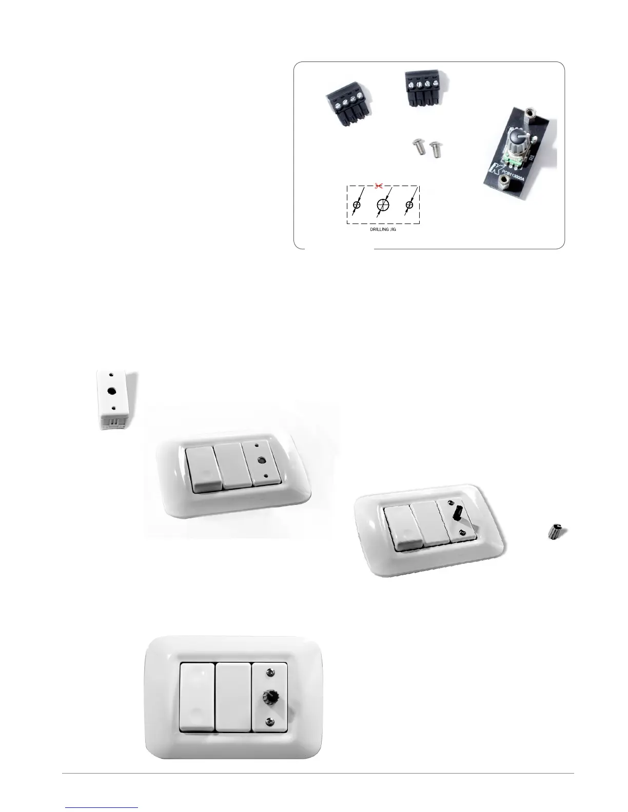
The KA-POT1 pack is composed of:
PCB with potentiometer
2 x screws M3X6
2 x 4-pin connector plugs
Drilling jig
Position the drilling jig on an appropriate box and make the three holes. Install your cap in a box for
switches and insert the PCB with the potentiometer coming out from the center hole. Secure with the
two included screws. Cover the potentiometer with the gray knob.
KA-POT1 UNPACKING
Ø7
Ø4
Ø4