Operating Manual BRAVO II
9
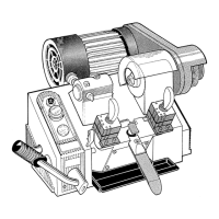
TO SET THE STOP POSITION OF THE CARRIAGE
Raise the carriage to the cutter. A space of 0.004” should remain between the cutter and the jaw. If this
is not the case then the adjustment should be carried out as follows:
1) Remove the chip tray.
2) Unlock the 0.39” nut (see fig. 14).
3) Adjust the space by turning the 0.119” allen screw through the hole in the base of the machine. Then
re-lock the nut with a 0.039mm wrench.
Fig. 14
MAINTENANCE
ATTENTION: for repairs or replacement of parts for maintenance, the ‘CE’ mark is guaranteed
only if original spare parts provided by the manufacturer are used.
The Bravo machine does not require special maintenance. It is recommended that the jaws and the
machine be kept free from chips as much as possible. DO NOT USE COMPRESSED AIR TO CLEAN
THE MACHINE.
WARRANTY
The manufacturer guarantees the machine as indicated in the warranty. No claims will be recognized if
the machine has been abused.
The manufacturer will not be responsible for accidents due to the machine not being grounded.
The manufacturer reserves the right to vary, at it’s discretion, the machine models, parts, and materials.
0.004”
0.119”
0.39”
 Loading...