Removing the fans
↻ A check has been performed to ensure there is no AC/DC voltage
present.
↻ DANGER!Risk of injury from starting fans: If the device is not com-
pletely disconnected from the voltage source, the fan may start up
unexpectedly and sever or injure limbs. This may also cause damage
to the fan and impair the functionality of the device.
↻ Cover hood for fans removed.
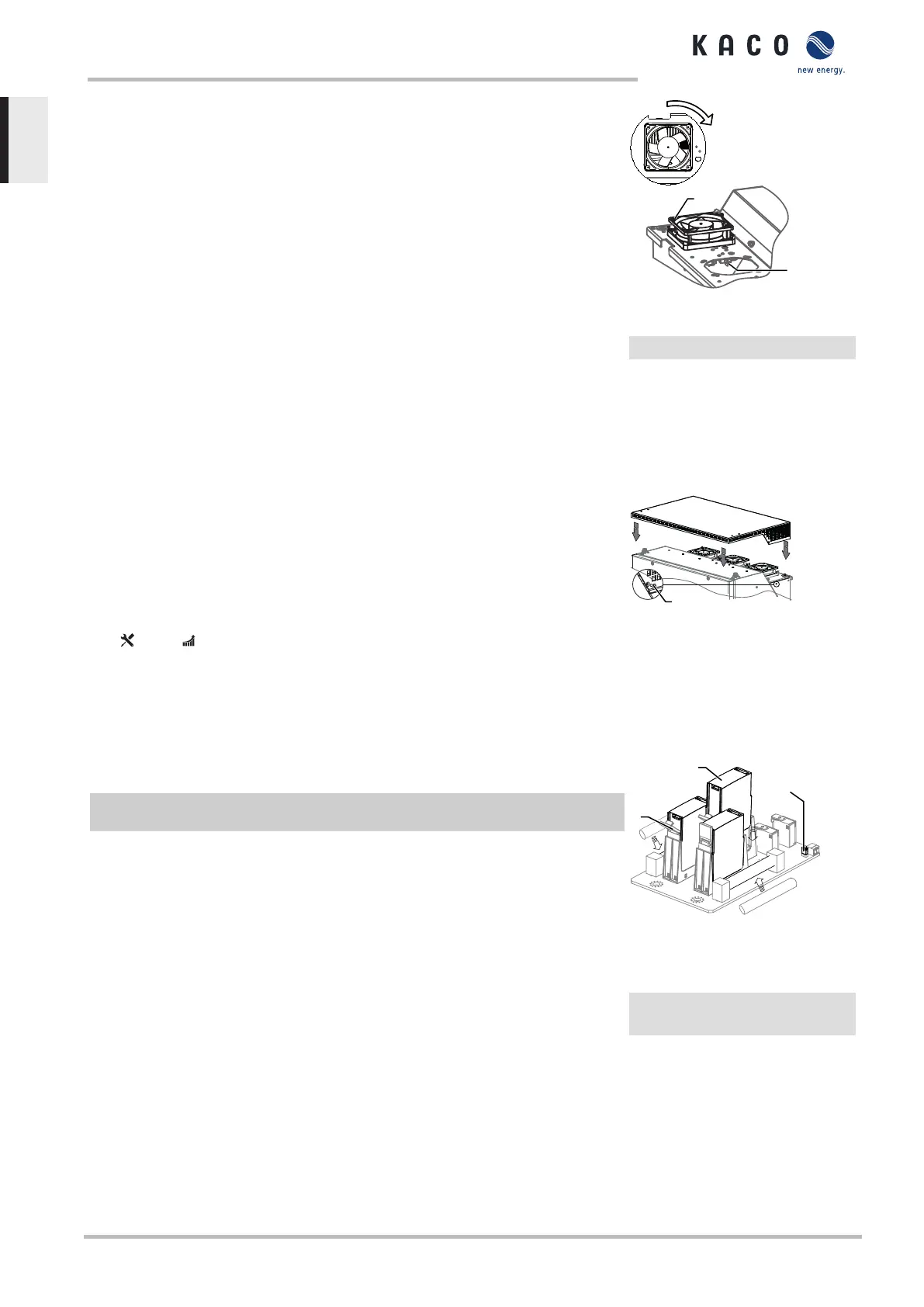
1. Wait until the 3 fans have stopped rotating.
2. Rotate the defective fan through approx. 10° in the clockwise direction
and remove it carefully using the collar.
3. Release the interlock and remove the connector plug from the inside of
the housing.
4. Remove the fan.
5. If necessary, clean the heat sink from above.
ð Install the replacement fan.
Fig.93: Removing the fans
1 Fans
2 Connector
Fitting the cover
↻ The fan has been correctly installed and all impurities in the area of the
cover have been removed.
1. Lift up the cover from both sides, place it on the mounting clips and care-
fully press it in.
2. Insert the fastening screws into the cover on both sides and tighten them
[ _T20 / 22 In-Ibs ].
ð You may now start up the device Start-up [See section8}Page38].
Fig.94: Fitting the cover
2 Fastening screw
11.4 Replacing overvoltage protection
Replace the DC overvoltage protection
F NOTE:If a fault appears on the status display of the overvoltage pro-
tection mode, the overvoltage protection should be replaced.
↻ NOTE:A check has been performed to ensure there is no AC/DC volt-
age present.
1. Opening the device Opening the device [See section7.2}Page25].
2. Unlock faulty modules via the locking latch.
3. Remove faulty modules individually from the DC base and replace with a
module of the same type.
. NOTE:The coding at the base plug-in position must match the cod-
ing on the module.
4. Insert the DC overvoltage protection modules into the DC base one after
another.
5. Secure new modules using the locking latch.
6. Ensure that all protective elements are properly secured.
ð Proceed with the installation of the device.
Fig.95: Inserting overvoltage mod-
ules
1 DC base
2 DC overvoltage protection
module (3 slots)
3 Jumper
11 | Maintenance and troubleshooting Manual
KACO blueplanet 87.0 TL3 KACO blueplanet 92.0 TL3 KACO blueplanet 105 TL3 KACO blueplanet 110 TL3
KACO blueplanet 125 TL3 KACO blueplanet 137 TL3 KACO blueplanet 150 TL3 KACO blueplanet 155 TL3
KACO blueplanet 165 TL3
Page 96
EN-US
 Loading...