Ensure that there is no ground fault
1. Measure the DC voltage between the protective earth (PE) and the positive cable of the PV generator.
2. Measure the DC voltage between the protective earth (PE) and the negative cable of the PV generator.
ð If stable voltages can be measured, there is a ground fault in the DC generator or its wiring. The ratio between
the measured voltages gives an indication as to the location of this fault.
3. Rectify any faults before taking further measurements.
4. Measure the electrical resistance between the protective earth (PE) and the positive cable of the PV generator.
5. Measure the electrical resistance between the protective earth (PE) and the negative cable of the PV generator.
ð In addition, ensure that the PV generator has a total insulation resistance of more than 2.0 MOhm, since the
device will not feed in if the insulation resistance is too low.
6. Rectify any faults before connecting the DC generator.
7.4.2 Recommended standard connection
DANGER
Risk of fatal injury due to electric shock (electric arc)!
Incorrect assignment of MPP trackers will seriously damage the device. Touching the live connections will result
in severe injury or death!
1. Make sure that each MPP tracker can be disconnected from all poles.
2. Observe recommended standard connection.
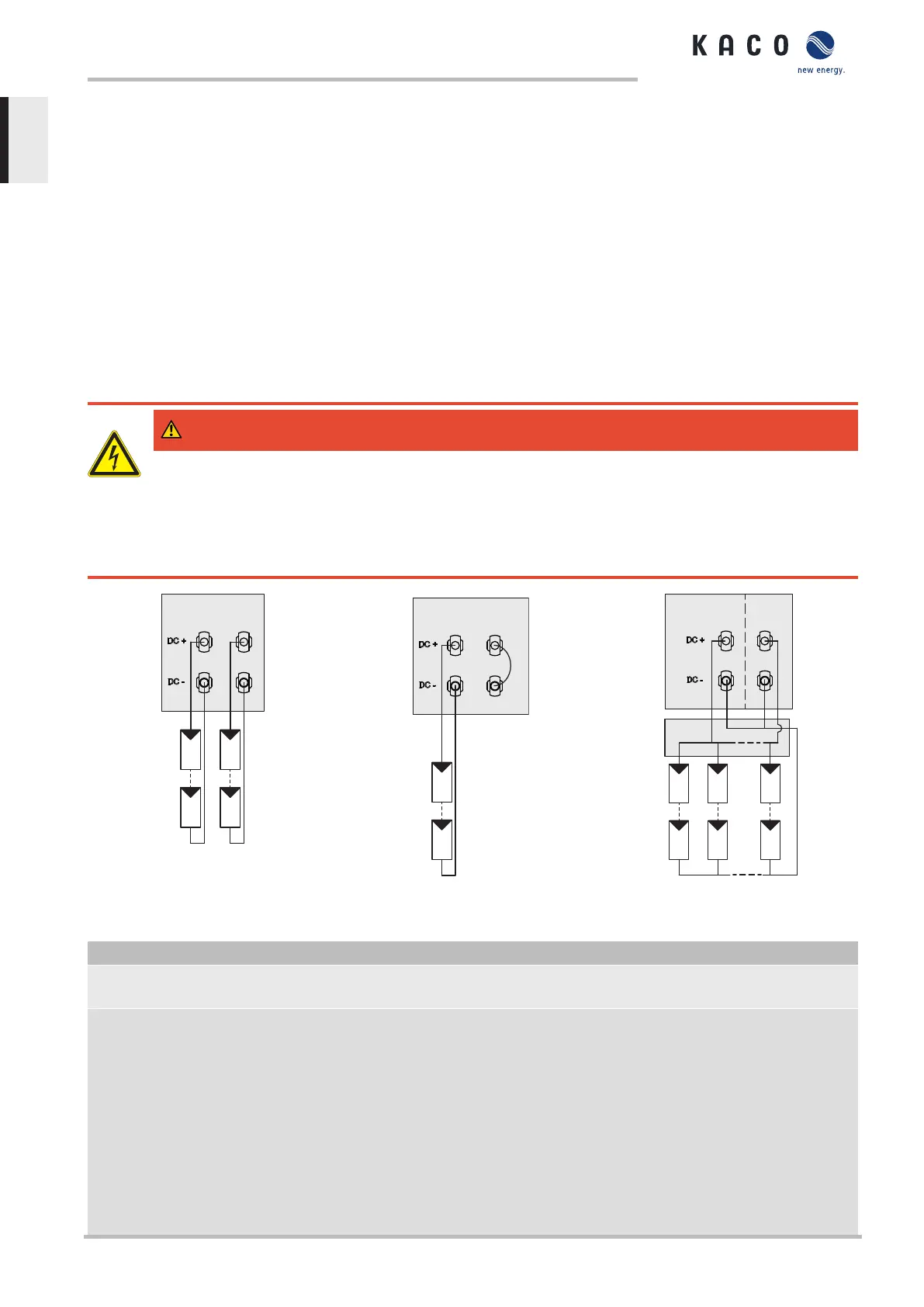
Fig.25: Recommended standard connection
Fig.26: Parallel input with Y-adapter, short-
circuits the unused MPP Tracker B
Fig.27: One generator parallel on both MPP
trackers
Possible wiring variants
2 PV generators for each MPP
tracker
1 PV generator for one tracker. The second
tracker is deactivated
1 PV generator parallel on both MPP
trackers
The MPP voltages of the two DC
strings can be different. They are
supplied by separate, independ-
ently operating MPP trackers
(MPP trackers A and B).
If one of the MPP trackers (A or B) is not used,
then it must be short-circuited, otherwise faults
can occur during the self-test of the unit and the
feed-in operation is not guaranteed. The short-
circuiting of an MPP tracker does not result in
the device being damaged.
The DC inputs can also be connected
in parallel. In this case, only lines with
the same MPP voltage may be con-
nected in parallel. (U
n1
=U
n2
=U
nm
).
The maximum permissible rated cur-
rent (DC) doubles with parallel con-
nection of both MPP trackers.
In case of a parallel input connection,
MPP trackers A and B must be
bridged. Parallel operation is auto-
matically recognised by the inverter
7 | Installation Manual
KACO blueplanet 3.0 TL3 KACO blueplanet 4.0 TL3 KACO blueplanet 5.0 TL3 KACO blueplanet 6.5 TL3 KACO
blueplanet 7.5 TL3 KACO blueplanet 8.6 TL3 KACO blueplanet 9.0 TL3 KACO blueplanet 10.0 TL3
Page 24
EN

 Loading...


