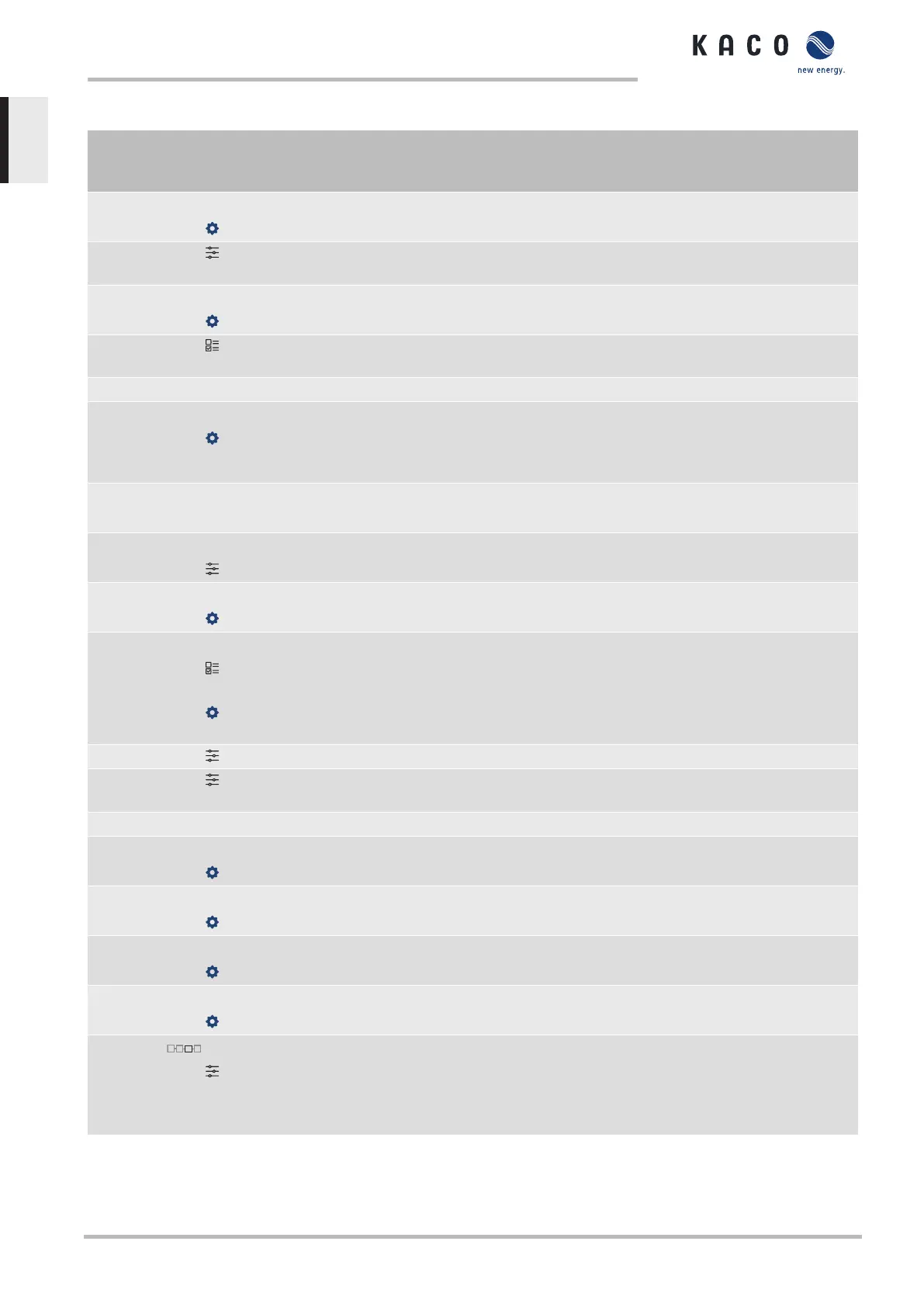
10.1.4 Parameters for reactive power control
Country-
spec. Set-
tings
Men
u
level
Display/
Setting
Action in this menu/meaning
cos-phi const.
1 – 0,3
Specified power factor
Over-excited | un-
der-excited
Reactive power mode Under-excited relates to inductive load, over-ex-
cited relates to capacitive load..
Q const.
0 – 100 [% S
max
]
Specification as a % of the maximum reactive power.
Over-excited | un-
der-excited
Reactive power operating type, under-excited corresponds to inductive
load, over-excited corresponds to capacitive load.
cos-phi(P/Plim)
Settling time
200 – 30000 [ms]
Determines the dynamic behaviour in the event of a change in the cosϕ
set value. With a change of the active power or the lock-in and lock out
voltage, the cosϕ is changed according to a PT-1 characteristic curve
with a settling time of 5Tau.
Lock-In voltage
23V – 287V
The control is activated above this voltage.
Lock-Out voltage
23V – 287V
The control is deactivated below this voltage.
Number of nodes
2 – 10
Specify the number of nodes for the cos ϕ/(p/pn) characteristic curve
1st node … 10th node
Voltage | Reactive
power | Excitation
0 – 100 [% S
max
]
Power of the node as a percentage of the maximum power.
For the 1stnode, the power must be 0%; for the last node, the power
must be 100%. The power values of the nodes must increase continu-
ously.
Note: Storage inverters only for feed-in operation
0 – 100 % cos ϕ of the node
Over-excited | un-
der-excited
Reactive power mode Under-excited relates to inductive load, over-ex-
cited relates to capacitive load.
Q(U) 10 nodes
Lock-In power
0 – 100 [% S
max
]
Power threshold, function is activated if limit value is exceeded.
Lock-Out power
0 – 100 [% S
max
]
Power threshold, function is activated if limit value is undershot.
Lock-in time
0 – 60 [s]
Length of time that the active power must remain below the lock-in
power level before control is deactivated.
Lock-out time
0 – 60 [s]
Length of time that the active power must remain below the lock-out
power level before control is deactivated.
Downtime
0-10000 [ms]
If the voltage switches from a characteristic curve section with Q=0 to a
characteristic curve section with Q≠0 under active control, then the re-
active power setting process is delayed by the set dead time. Once the
dead time has expired, the control circuit is no longer subject to a delay
and the set transient time determines the transient behaviour.
10 | Specifications Manual
KACO blueplanet 3.0 TL3 KACO blueplanet 4.0 TL3 KACO blueplanet 5.0 TL3 KACO blueplanet 6.5 TL3 KACO
blueplanet 7.5 TL3 KACO blueplanet 8.6 TL3 KACO blueplanet 9.0 TL3 KACO blueplanet 10.0 TL3
Page 58
EN
 Loading...


