Country-
spec. Set-
tings
Men
u
level
Display/
Setting
Action in this menu/meaning
Constant k negative se-
quence dip
Constant k negative se-
quence swell
k 0 – 10 2
Amplification factor for the negative sequence used in the calculation of
the reactive current using formulae (2) and (4) Can be configured inde-
pendently for drops and spikes.
Constant k positive se-
quence dip &
Constant k positive se-
quence swell
k 0 – 10 2
Amplification factor for the negative sequence used in the calculation of
the reactive current using formulae (2) and (4) Can be configured inde-
pendently for drops and spikes.
Dead band
0 - 100 [% Uref]
10.0
Dynamic grid support through fast feeding of residual current activated
in the case of voltage events with a voltage change greater than the
dead band.
Dynamic reactive cur-
rent only
Off | On
Standard: The reactive current according to the formulae(2) and(4) is
fed as additional reactive current. The means that sum of the pre-fault
and additional reactive current is fed in.
Only dynamic: The reactive current according to the formulae (2) and
(4) is fed in as absolute reactive current. This means that regardless of
the reactive current before the voltage event, only the reactive current
is fed in according to the formulae(2) and(4) is fed in during the voltage
event.
Dead band mode
Mode 1 | Mode 2
Mode 1: When calculating the reactive current, the value of the dead
band is not subtracted from the amount of voltage change.
As such, formula (2) applies to overvoltage and undervoltage incidents.
Mode 2: When calculating the reactive current, the value of the dead
band is subtracted from the amount of voltage change. For overvoltage
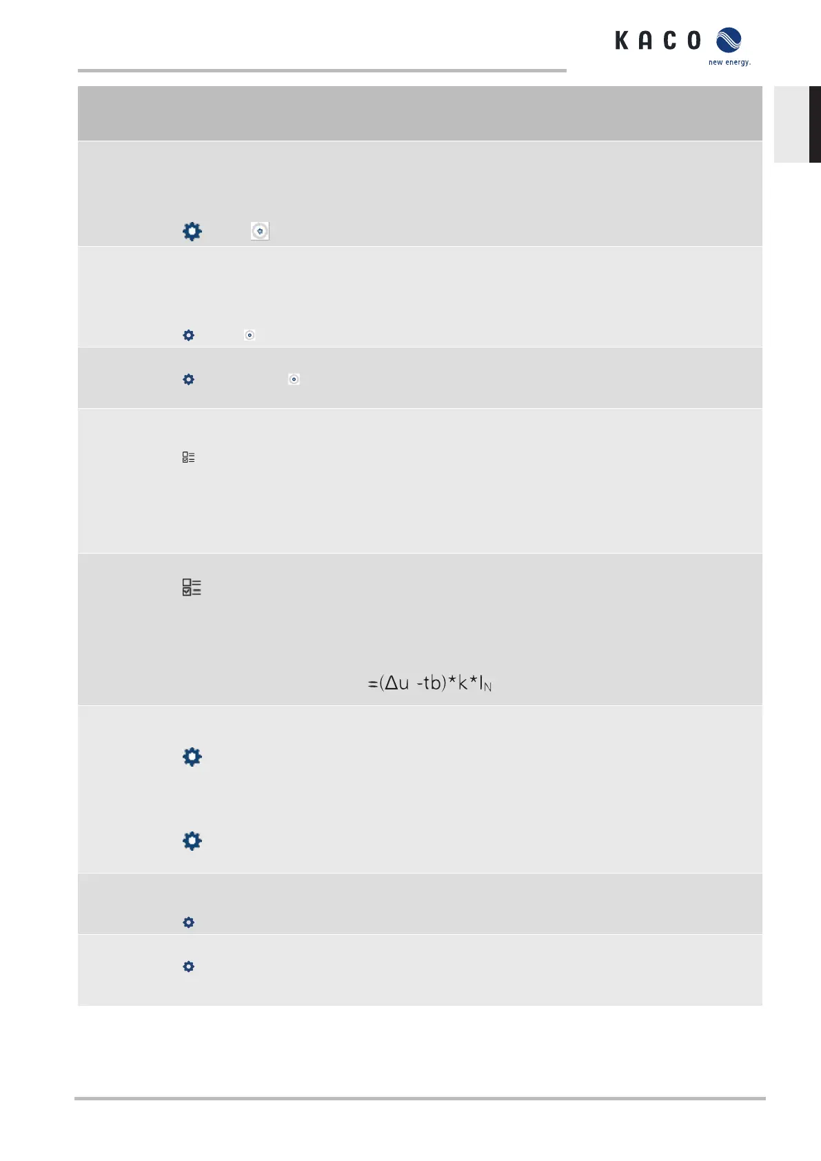
and undervoltage events, formula (4) therefore applies:
Minimum operating
voltage
45 – 125.0 [%
Unom] &
Maximum operating
voltage
45 – 125.0 [%
Unom]
Dynamic grid support via fast feeding of residual current is activated on
voltage events with at least one phase/phase or phase/neutral con-
ductor voltage outside the configured normal operating voltage range.
Dynamic grid support via fast feeding ore residual current is deactivated
when the voltage returns to the normal operating voltage range.
Reactive current limita-
tion
0 – 100 % [ % Imax]
The reactive power component of the fast feeding of residual current is
limited to permit a defined proportion of active power components.
Minimum support time
1000 – 15000 ms
If due to a voltage jump in accordance with formula (1) and the con-
figured dead band is activated, the dynamic grid support is deactivated
via fast feeding of residual current after the minimum support time
elapses.
Manual Specifications | 10
KACO blueplanet 3.0 TL3 KACO blueplanet 4.0 TL3 KACO blueplanet 5.0 TL3 KACO blueplanet 6.5 TL3 KACO
blueplanet 7.5 TL3 KACO blueplanet 8.6 TL3 KACO blueplanet 9.0 TL3 KACO blueplanet 10.0 TL3
Page 67
EN
 Loading...


