Extract from Service Manual
1 --- 2
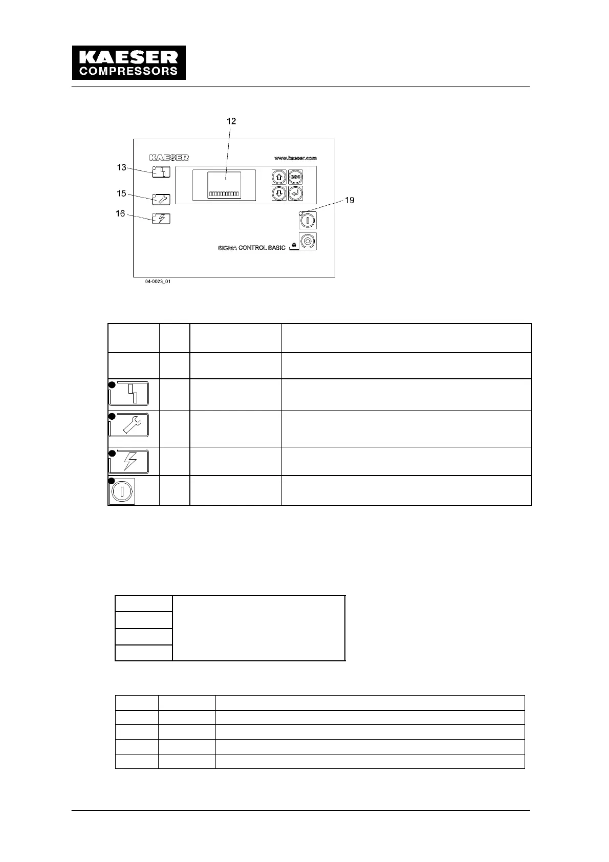
Fig. 2 Indicators
Symbol
Item Description Function
12 Display field (Dis-
play)
Alphanumeric display with 4 lines.
13 Alarm Blinks red when an alarm occurs.
Lights continuously when acknowledged.
15 Service/warning
LED
Lights continuously yellow for:
--- maintenance work required
--- warning message
16 Controller voltage Lights green when the power supply to the controller
is switched on.
19 Machine ON Lights green when the machine is switched on.
Tab. 2 Displays
1.2 Function Description
1.2.1 Display field layout (Display, Position 12, Fig. 2)
Line 1
x x . x b a r
Line 2
y y ˚ C
Line 3 z 0 0 0 0 h
Line 4 1 2 3 4 5 6 7 8 S p T i
Fig. 3 Display layout (Display)
Line Display Meaning
1 XX.X Current system pressure in bar, psi or MPa.
2 yy Current airend discharge temperature (ADT) in ˚ C or ˚ F.
3 0...9 Parameter display and setting (see Tab. 4)
4 1,2... Alarm and warning messages (see Tab. 5 and Tab. 6)
Tab. 3 Display field (Display)