Fig. 1 Maximum relative humidity of intake air ..................................................................................... 6
Fig. 2 Location of safety signs .............................................................................................................. 23
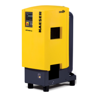
Fig. 3 Enclosure overview .................................................................................................................... 27
Fig. 4 Machine layout ........................................................................................................................... 28
Fig. 5 Refrigeration dryer ...................................................................................................................... 29
Fig. 6 Machine mountings .................................................................................................................... 29
Fig. 7 Keys – overview ......................................................................................................................... 33
Fig. 8 Indicators .................................................................................................................................... 34
Fig. 9 Recommended machine placement and dimensions [mm] ........................................................ 38
Fig. 10 Compressed pipework ................................................................................................................ 41
Fig. 11 Condensate drain dimensions [mm] ........................................................................................... 43
Fig. 12 Connections SIGMA CONTROL BASIC ................................................................................... 43
Fig. 13 Inlet valve filling port ................................................................................................................... 48
Fig. 14 MODULATING control: Setting the shut-off valve ...................................................................... 49
Fig. 15 Location of the interlock switch .................................................................................................. 49
Fig. 16 Switching On and Off ................................................................................................................. 52
Fig. 17 Switching off in an emergency ................................................................................................... 53
Fig. 18 Acknowledging messages .......................................................................................................... 55
Fig. 19 Filter mat for the air and oil cooler .............................................................................................. 63
Fig. 20 Switching cabinet ventilation ...................................................................................................... 64
Fig. 21 Filter mat for the air and oil cooler .............................................................................................. 65
Fig. 22 Air filter maintenance .................................................................................................................. 66
Fig. 23 Drive Belt Maintenance .............................................................................................................. 67
Fig. 24 Checking the cooling oil level ..................................................................................................... 70
Fig. 25 Venting the machine ................................................................................................................... 71
Fig. 26 Replenishing the cooling oil ........................................................................................................ 72
Fig. 27 Changing the cooling oil, oil separator tank ............................................................................... 75
Fig. 28 Changing the cooling oil, heat recovery system ......................................................................... 76
Fig. 29 Changing the oil filter .................................................................................................................. 77
Fig. 30 Changing the oil separator cartridge .......................................................................................... 79
Fig. 31 Refrigeration dryer ...................................................................................................................... 80
Fig. 32 Checking condensate drainage .................................................................................................. 81
Fig. 33 Condensate drain maintenance ................................................................................................. 82
Fig. 34 Transport with a forklift truck ...................................................................................................... 91
Fig. 35 Transport with a crane ................................................................................................................ 92
List of Illustrations
9_5717 20 E
Service Manual Screw Compressor
ASK T SIGMA CONTROL BASIC
v