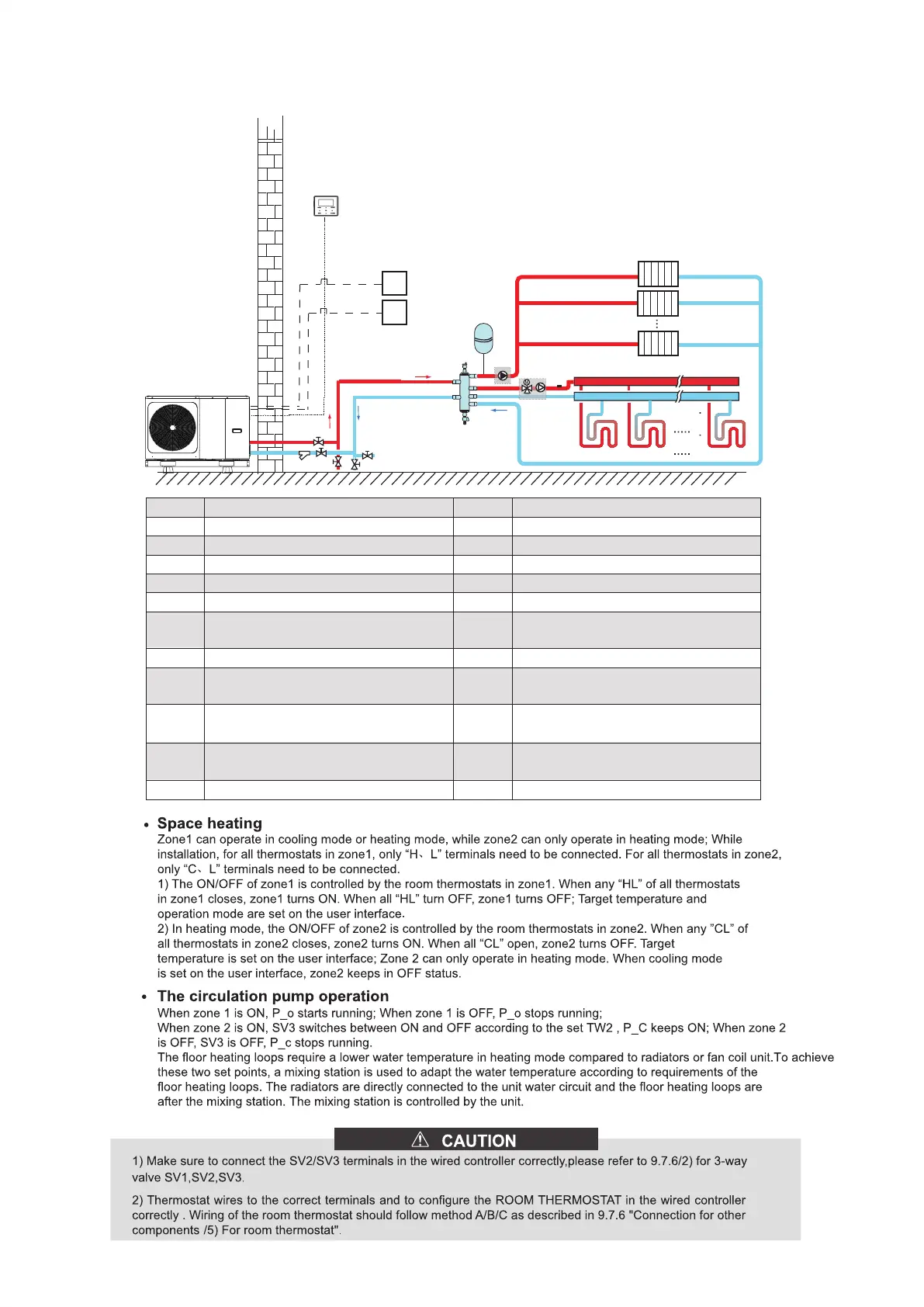
8.2.3 Double zone control
Code Assembly unit Code Assembly unit
1 Main unit
2
4
User interface
4.1
Balance or buffer tank (Field supply)
19
4.2
Automatic air purge valve
Collector/distributor (Field supply)
5
Drainage valve
2 3
P_o: zone 1 circulation pump (Field supply)
RT 1
Low voltage room thermostat (Field
supply)
23.1
Mixing station (Field supply)
RT8
High voltage room thermostat (Field supply)
23.2
SV3: Mixing valve (Field supply)
Tw2
Zone 2 water flow temperature sensor
(Optional)
12
P_c: zone 2 circulation pump (Field supply)
FHL
1…n
Floor heating loop (Field supply)
RAD.
1...n
Radiator (Field supply)
Filter (Accessory)
10
Expansion vessel
(Field supply)
14
Shut-off valve (Field supply)
16
Drainage valve (Field supply)
15
Filling valve (Field supply)
4
4.2
4.1
10
FHL1 FHL2 FHLn
19
Outdoor
Indoor
Tw2
23
23.1
23.2
5
RAD.1
RAD.2
RAD.n
ZONE1
ZONE2
RT8
RT1
2
Modbus
15
16
14
12
14
16
1
108