The tekmarNet®4 Thermostat 540e is a sophisticated control device designed for managing single-stage heating, single-stage cooling, and a single fan in a building. It is compatible with the tN4 communication system, allowing it to integrate into a larger network of controls for optimized performance and energy savings.
Function Description:
The primary function of the 540e thermostat is to maintain a desired room temperature by controlling heating and cooling equipment and a fan. It offers various operating modes including Auto, Cool, Heat, Vent, and Off. In Auto mode, it automatically switches between heating and cooling to maintain both a Set Room Heat and Set Room Cool temperature, ensuring these setpoints are always at least 3°F (1.5°C) apart to prevent system conflicts. The thermostat can operate as a schedule member, following a programmable setback schedule if available from a schedule master device on the tN4 bus. It also supports "Scenes" for system-wide manual overrides, allowing all participating thermostats to change their operating temperature simultaneously for events like vacations or holidays.
The 540e incorporates an "Optimum Start" feature, which intelligently predicts the heat-up or cool-down rate of the room to ensure the desired temperature is reached by the scheduled time. For heating, it can be configured for either hydronic or other heat sources (e.g., furnace, electric), with hydronic systems benefiting from indoor temperature feedback and synchronized heating cycles for improved efficiency and comfort. Cooling operation includes a fixed minimum on-time of 2 minutes and an off-time of 5 minutes to prevent short cycling of equipment. The fan can be set to operate with cooling only (Fan Mode 1) or with both heating and cooling (Fan Mode 2), and includes a post-purge feature to continue operation for 30 seconds after heating or 10 seconds after cooling. Ventilation can also be enabled, allowing the fan to run for a minimum percentage of time during occupied and unoccupied events.
Important Technical Specifications:
- Power: 24 V ±10% 50 Hz 1.8 VA (56 VA fully loaded)
- Relays: 24 V (ac) 2 A
- Wiring: Requires 6 wires (tN4, C, R, W, G, Y)
- Temperature Range: Setpoints can be adjusted between 40 to 85°F (4.5 to 29.5°C) for both heating and cooling.
- Freeze Protection: Automatically turns on heating if room temperature falls below 40°F (4.5°C).
- Communication: tN4 Communication Compatible, supports automatic and manual addressing on the tN4 bus.
- Compliance: CE Approved
Usage Features:
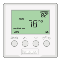
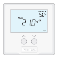
- Display: Features a main display for current room temperature and mode, and a secondary display for additional information like outdoor temperature, setpoints, and system status. Symbols clearly indicate heat on, cool on, fan on, occupied/unoccupied modes, communication status, and warnings.
- Button Operation: Intuitive buttons for mode selection (Auto, Cool, Heat, Vent, Off), temperature adjustment (up/down arrows), and local override. The local override button allows users to switch between manual override temperatures (occupied, unoccupied) or follow the programmable schedule.
- User Settings Menu: Accessible through a combination of button presses, allowing users to view and adjust settings such as °F or °C display, software version, and tN4 address.
- Installer Adjust Menu: A dedicated menu for installers to configure advanced settings like heat and cool setpoints for different scenes, fan mode, ventilation settings, heat cycles per hour, and schedule selection.
- Outdoor Temperature Display: When connected to a tN4 system with an outdoor sensor, the outdoor temperature is shown on the display.
- Backlight: The display backlight turns on for 30 seconds after any button press.
- Warm Weather Shut Down (WWSD): Prevents the heating system from operating if the outdoor temperature exceeds a set WWSD temperature, indicated by a WWSD icon. This feature is activated and adjusted via the tN4 System Control.
- Cool Group Master: Can be configured as a master for a cooling group, coordinating cooling operations with other member thermostats on the tN4 bus by averaging their air temperature readings. This prevents simultaneous heating and cooling.
- Exercising: When connected to a tN4 System Control and set for hydronic heating, the thermostat exercises the heat relay for 10 seconds every 3 days to prevent zone valves or pumps from failing due to precipitate buildup.
- Zone Test: Allows installers to individually turn on zones via the tN4 System Control for wiring verification.
- Max Heat: An installer-only feature to turn on all heating zones and operate equipment at 100% output for rapid building heating (e.g., for concrete curing), lasting up to 24 hours or until manually stopped.
- Flushing: If connected to a tN4 System Control with the flushing feature enabled and set for hydronic heating, a "FLUSH" icon will appear during the flushing operation.
Maintenance Features:
- Error Messages: The thermostat displays specific error codes (e.g., E01 for Control Error, Err for Bus Error, LIM for Device Limit, ADDRESS for Address Error, SH- for Room Sensor Short Circuit, OPn for Room Sensor Open Circuit, MSE for Cool Master Error) to assist in troubleshooting. These messages provide guidance on how to resolve issues, such as checking wiring, adjusting settings, or contacting a sales representative for hardware faults.
- Cleaning: The thermostat's exterior can be cleaned with a damp cloth moistened with water; solvents or cleaning solutions should not be used.
- Warranty: The product comes with a manufacturer's pass-through warranty covering defects in workmanship and materials, provided the product is installed and used in compliance with kanmor's instructions. The warranty period is 24 months from the production date or 12 months from the documented installation date if installed within 24 months of production.