Do you have a question about the Kanmor tekmarNet 4 and is the answer not in the manual?
Details the purpose and operation of the tekmarNet® 4 Thermostat 538e.
Lists the main functional capabilities of the thermostat, such as wiring requirements and sensor integration.
Highlights the advantages of using the thermostat, focusing on energy savings and system efficiency.
Warns about potential damage and injury from improper installation and safety standards.
Lists the necessary tools and materials required for installing the thermostat.
Provides guidelines for selecting an optimal placement for the thermostat.
Explains the procedure for detaching the thermostat from its base.
Details how to mount the thermostat base, including using an adapter plate.
Illustrates how to connect the thermostat and optional auxiliary sensors.
Provides steps to test power supply and wiring integrity.
Describes how to test the thermostat's heat relay functionality.
Outlines procedures to test the communication bus for short or open circuits.
Explains the correct method for reattaching the thermostat to its base.
Gives instructions for safely cleaning the exterior of the thermostat.
Details the function of each DIP switch for thermostat configuration.
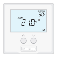
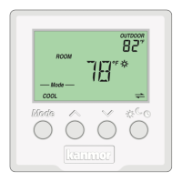
Describes the main and secondary display areas and their indicators.
Explains how to use the thermostat's buttons for temperature adjustment.
Defines the various symbols displayed on the thermostat screen.
Sets the room heating temperature for specific events like '*' or 'C'.
Sets the room heating temperature for the 'Away' scene.
Sets the floor heating temperature for specific events like '*' or 'C'.
Configures the backlight behavior: Off, 30 seconds, or On.
Selects the display units between Fahrenheit (°F) and Celsius (°C).
Displays device type, software version, and thermostat address.
Sets the upper limit for room heating temperature for '*' and 'C' events.
Sets the minimum temperature limit for room heating.
Sets the minimum floor temperature, ensuring floor heating.
Sets the maximum floor temperature to protect floor covering.
Allows the thermostat to follow a programmed schedule.
Enables or disables the built-in air temperature sensor.
Selects the type of auxiliary sensor (Room, Outdoor, Floor).
Configures automatic cycling or synchronization with other thermostats.
Determines pump operation (On, Delay, Off) for hydronic systems.
Manually sets or automatically addresses the thermostat on the network.
Returns the thermostat to normal operation from the settings menu.
Explains how the thermostat controls heating based on room or floor sensors.
Describes how the thermostat activates heating to prevent freezing.
Details the periodic relay exercise to prevent valve/pump failure.
Explains the system flushing feature for open-loop hot water systems.
Defines the thermostat's role in controlling the system supply pump.
Explains how thermostats form groups to coordinate cooling.
Describes how DHW tank recovery may affect heating zones.
Explains how high outdoor temperatures can shut off the heating system.
Details how the thermostat follows schedules for energy savings.
Explains how scenes override schedules for energy saving or convenience.
Indicates settings could not be read; reloads factory defaults.
Signifies a short or open circuit on the tekmarNet® communication bus.
Occurs when the number of devices on the bus exceeds 24.
Indicates a duplicate tekmarNet® address assignment.
Covers short or open circuit faults for the built-in room sensor.
Occurs when a cooling group member lacks a master thermostat.
Addresses short or open circuit faults for the auxiliary floor sensor.
Covers short or open circuit faults for the auxiliary outdoor sensor.
Details short or open circuit faults for the auxiliary room sensor.
Provides corrective actions for common issues like 'No Heat' or temperature inaccuracies.
A template for recording thermostat installation settings and job details.
Lists technical data including weight, dimensions, power, and sensor compatibility.
Outlines the limited warranty period, coverage, and exclusions.
Details the process for returning defective products for warranty claims.
| Brand | Kanmor |
|---|---|
| Model | tekmarNet 4 |
| Category | Thermostat |
| Language | English |