4 of 24© 2011 D 538e - 02/11
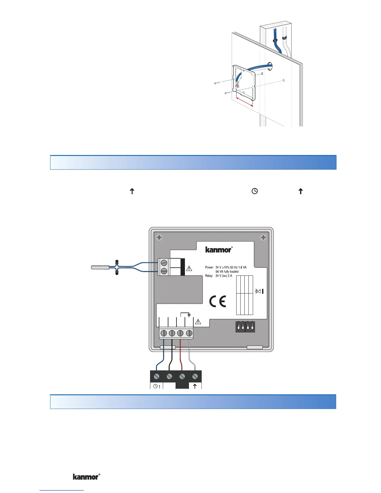
If a switch box was not used, mount the
thermostat directly to the wall.
Feed the wiring through the openings in
the back of the thermostat.
Use screws in the screw holes to fasten the
thermostat to the wall. At least one of the
screws should enter a wall stud or similar
rigid material.
•
•
Stud
60 mm
screwhole
Thermostat
Base
Wall
Mounted on wallboard
Thermostat Wiring
The thermostat operates a single heating system zone.
Connect tN4, N, L, and terminals on the thermostat to the 1, L, N, and terminals
on the Wiring Center 375x.
Connect the optional auxiliary sensor wires to the sensor terminals 5 and 6.
12 34
Wiring Center 375x
Slab Sensor 079e
OR
Outdoor Sensor 070e
OR
Indoor Sensor 076e, 084
tNt 538e
538e
One Stage Heat
Made in
Canada
Mmm YYYY
Lot # 12345
1001-06
tN4
1
N
2
L
3
K
4
6
S1
5
Com
Switch Settings:
For instructions see brochure
Setback
Scene
None
Lock
ON
Unlock
Cool Member 1
Off
Off
No Power
N
L
Testing the Thermostat Wiring
Testing the Power
---------------------------------------------------
---------------------------------------------------
1. Remove the front cover from the thermostat.
2. Use an electrical test meter to measure (ac) voltage between the L and N
terminals. The reading should be 24 V (ac) +/– 10%.
3. Install the front cover.