INSTALLATION MANUAL / USER MANUAL
REMOTE CONTROL PANELS RC200 / RC200 NVG
PAGE: 11
OCT 03/2013
D. Acceptance test procedure
Perform an RCP test (Refer to D. RCP operational tests, page 15).
5. Working mode
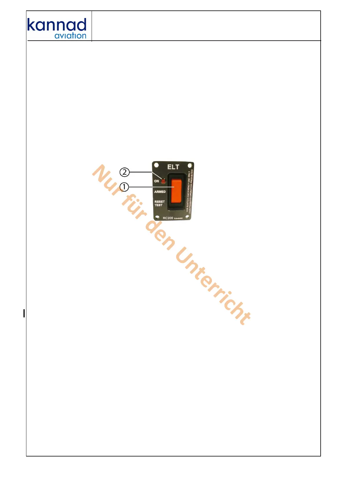
A. Controls
The following elements are to be found on the RC200 remote control
panels:
1. a 3-position switch (ON, ARMED, RESET & TEST);
2. a red visual indicator.
Figure 8: RCP controls
The visual indicator gives an indication on the working mode of the
beacon:
- After the self-test:
• one long flash indicates that the system is operational and that no
error were found;
• a series of short flash indicates the test has failed.
- In operation mode:
• periodic flashes during homer transmissions;
• long flash during 406 transmission.
B. Working mode information
The RC200 remote control panels enable remote control and remote
monitoring of the KANNAD ELTs provided that the ELT switch is in
armed position.
(1) Remote control
Remote control is done through a 3-position switch:
1. ON (transmission) enables manual activation of the ELT;
2. ARMED (stand by mode to enable automatic activation by the shock
sensor of ELT) is an idle position. Unless there is an emergency, the
switch must stay in this position.
Nur für den Unterricht