LS30 CONTROLLER INSTALLATION AND OPERATING GUIDE
3
1. GENERAL
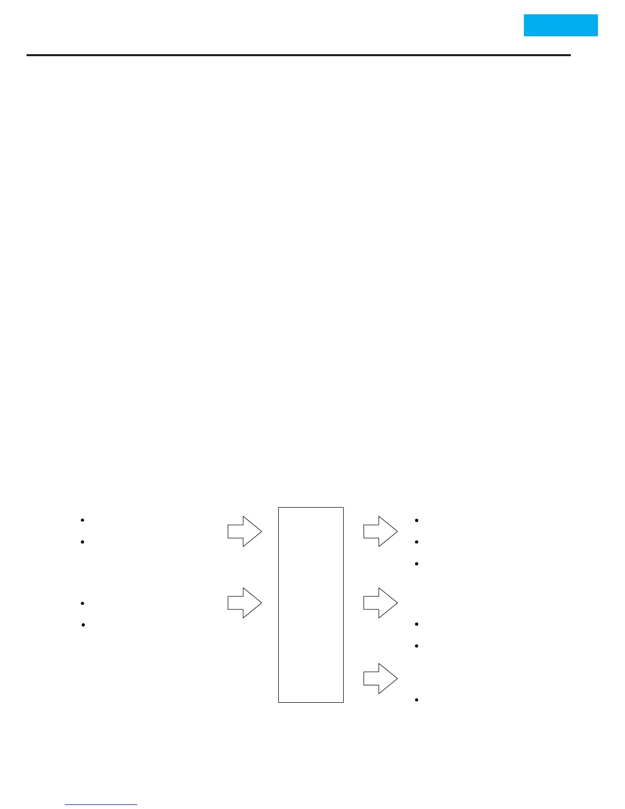
1.2 Block Diagram
1.1 Device Descripon
LS30 Controller devices are the devices that transfer data to
user and automaon systems by using the data received from
MLG30 and LS30 Level Control Equipments. Sensor data related
with level sensors are transferred to LS30 Controller and level
changes can be monitored from display screen. With this data
can be controlled by 3 each NO(Normally Open) + NC(Normally
Closed) relay contacts and motor, pump, on-o valve, solenoid
valve, audible or/illuminated alarm type of three dierent de-
vices that has been integrated to the device. Also by means of
4-20 mA, 0- 10 V analog signal outputs or RS 485 Modbus com-
municaon protocol connecon can be made with automaon
systems.
LS30 DIGITAL CONTROLLER