LS30 CONTROLLER INSTALLATION AND OPERATING GUIDE
13
3.8 Cabling
The cable connecons should be 1,5 mm
2
in cross secon. In
contrary the terminal connecons can not be made. At general
cabling mul wired and nny cables should be preferred for ex-
tending life cycle of device and to eliminate disconnuity pos-
sibility that may occur by oxidaon. At LS30 and MLG30 sensor
input connecons 3x0,75mm
2
cross secon cables can be used.
For controlling of 'V' outputs in case there is not automaon
connecon measurement can be taken from 9&10 terminals of
'V DC' stage of measurement devices. The measurement values
should give results close to below menoned formula.
(for 0-10 V) V value = % value on the display / 10
(for 10-0 V) V value = (100 - % value on the display) / 10
3.7 Connecon of RS485 Serial Comminicaon Interface
Please ask for RS485 Interface Connecon.
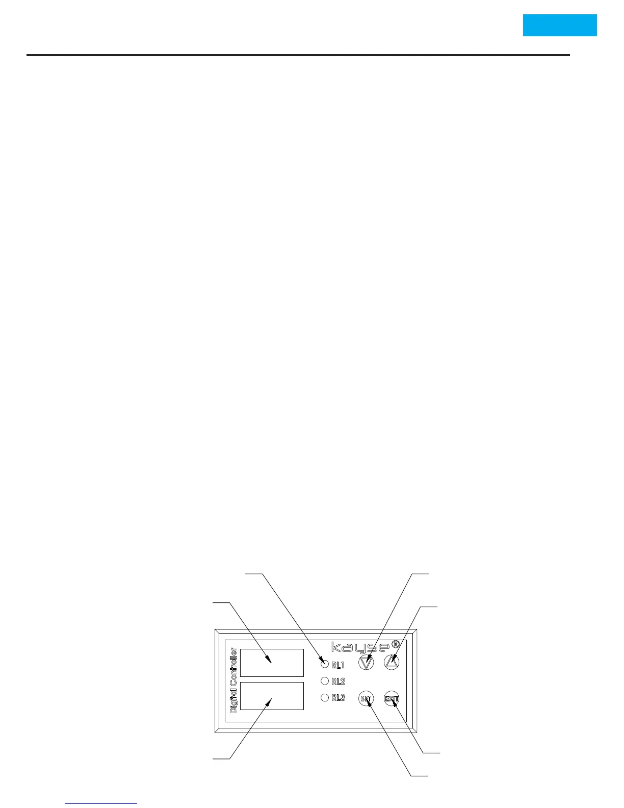
4. PROGRAMMING
Upper Display
(Level and Parameter
Levels)
Bottom Display
(Parameters)
Relay Working Leds
"Down Arrow" Button
"Up Arrow" Button
"Exit" Button