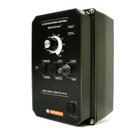
KBAC SERIES INSTALLATION AND OPERATION MANUAL
23
13 – DIAGNOSTIC LEDs
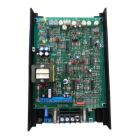
The drive contains two diagnostic LEDs mounted on the enclosure cover to display the drive's operational status.
WARNING! Do not depend on the PWR LED as a guaranteed power off condition. Be sure the main power switch or circuit breaker is in
the "OFF" position before servicing this drive.
13.1 – POWER ON LED (PWR)
The "PWR" LED will illuminate green when the AC Line is applied to the drive.
13.2 – STATUS LED (ST)
The "ST LED is a tricolor LED which provides
indication of a fault or abnormal condition. The
information provided can be used to diagnose
an installation problem such as incorrect input
voltage, overload condition, and drive output
miswiring. It also provides a signal which
informs the user that all drive and
microcontroller operating parameters are
normal. Table 6 summarizes the "ST" LED
functions.
14 – OPTIONAL ACCESSORIES
Detailed instructions are provided with all accessories. See Table 7.
TABLE 7
OPTIONAL ACCESSORIES
Description KBAC-24D KBAC-27D KBAC-29 KBAC-29 (1P) KBAC-45 KBAC-48
KBAC-217 Series
KBAC-416 Series
Forward-Stop-Reverse Switch Kit: Provides
motor reversing and stop functions. Mounts on the
enclosure cover and is supplied with a switch seal
to maintain liquidtight integrity.
9480 9480 9480 9480 9480 9480 8888
On/Off AC Line Switch Kit: Disconnects the AC
Line. Mounts on the enclosure cover and is
supplied with a switch seal to maintain liquidtight
integrity.
9482 9523 9523 9523 9532 9532
"S" Suffix Models
(Factory Installed)
Run-Stop-Jog Switch Kit: Selects speed setting
from either the Main Speed Potentiometer or the
JOG Trimpot. Mounts on the enclosure cover and
is supplied with a switch seal to maintain liquidtight
integrity.
9340 9340 9340 9340 9340 9340 8889
SIAC-PS Signal Isolator Kit: Provides
isolation between a non-isolated signal
source and the drive. Mounts on the drive’s
PC board with four snap-ins.
2G 9600C 9600C 9600C 9600C 9600C 9600C —
3G
1
8890 8890 8890 8890 8890 8890 8890
Auto/Manual Switch Kit: When used with the
Signal Isolator, it selects remote process signal or
the Main Speed Potentiometer. Mounts on the
enclosure cover and is supplied with a switch seal
to maintain liquidtight integrity.
9481 9481 9481 9481 9481 9481 8891
SIAC-PS Signal Isolator Kit and Auto/Manual
Switch Kit
9605 9605 9605 9605 9605 9605 8893
AC Line Filter Kit
2
: Provides Class A RFI
(EMI) suppression. Installs onto the drive’s
PC board with quick-connect terminals.
"S" Suffix filter is used when On/Off AC Line
Switch is installed. "NS" Suffix filter is used
when On/Off AC Line Switch is not installed.
"S"
Suffix
9507 9512 9479 — 9479 9479
"F" Suffix Models
(Factory Installed)
"NS"
Suffix
9507 9512 9515 — 9515 9515
Liquidtight Fittings Kit: Provide a liquidtight seal
for wiring the drive.
9526 9526 9526 9526 9526 9526 8892
Notes: 1. Third Generation (3G) drives are marked "(3G)" on the product label. 2. Complies with CE Council Directive 89/336/EEC Industrial
Standard.
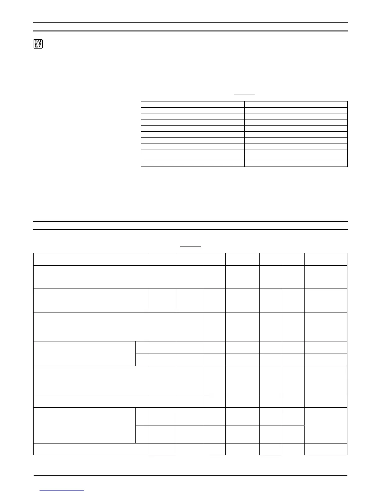
TABLE 6
DRIVE OPERATING CONDITION AND STATUS LED INDICATOR
Drive Operating Condition Flash Rate
1
and LED Color
Normal Operation Slow Flash Green
Overload (120%
160% Full Load) Steady Red
2
I
2
t (Drive Timed Out) Quick Flash Red
2
Short Circuit Slow Flash Red
Undervoltage Quick Flash Red / Yellow
3
Overvoltage Slow Flash Red / Yellow
3
Stop Steady Yellow
Stand-By
4
Slow Flash Yellow
Input Phase Loss
5
Rapid Flash Yellow
Overtemperature Trip
6
Slow / Quick Flash Red
1
Notes: 1. Slow Flash = 1 second on and 1 second off. Quick Flash = 0.25 second on and
0.25 second off. 2. When the Overload is removed, before the I
2
t times out and trips the
drive, the "ST" LED will flash green. 3. When the Undervoltage or Overvoltage condition is
corrected, the "ST" LED will flash Red / Yellow / Green. 4. Only if the Forward-Stop-Reverse
Switch is installed. 5. KBAC-29, with three-Phase AC Line input and KBAC-45, 48.
Rapid Flash = 4 mSec on and 6 mSec off. 6. KBAC-217, 416 Series only.