KBAC SERIES INSTALLATION AND OPERATION MANUAL
3
TABLE OF CONTENTS (CONTINUED)
Figure Page
1 General Connection Diagram ........................................................................................................................................................................... 4
2 Maximum Allowed Motor Torque vs. Speed ..................................................................................................................................................... 5
3 Open Ventilated Motor with External Fan Cooling ............................................................................................................................................ 5
4 KBAC-24D Drive Layout ................................................................................................................................................................................... 8
5 KBAC-27D Drive Layout ................................................................................................................................................................................... 9
6 KBAC-29, 29 (1P), 45, 48 Drive Layout .......................................................................................................................................................... 10
7 KBAC-217, 217S, 217F, 217SF, 416, 416S, 416F, 416SF Drive Layout ....................................................................................................... 11
8 KBAC-24D Mechanical Specifications ............................................................................................................................................................ 12
9 KBAC-27D, 29, 29 (1P), 45, 48 Mechanical Specifications ............................................................................................................................ 13
10 KBAC-217, 217S, 217F, 217SF, 416, 416S, 416F, 416SF Mechanical Specifications .................................................................................. 14
11 KBAC-24D, 27D, 29 (1P) AC Line Input, Motor, and Ground Connections.................................................................................................... 15
12 KBAC-29, 45, 48 AC Line Input, Motor, and Ground Connections................................................................................................................. 16
13 KBAC-217, 217S, 217F, 217SF, 416, 416S, 416F, 416SF AC Line Input, Motor, and Ground Connections ................................................ 16
14 Remote Main Speed Potentiometer Connection ............................................................................................................................................ 16
15 Remote Start/Stop Switch Connection with Normally Open Stop Contact ..................................................................................................... 17
16 Remote Start/Stop Switch Connection with Normally Closed Stop Contact ................................................................................................... 17
17 Start/Stop Function Eliminated ....................................................................................................................................................................... 17
18 Voltage Following Connections ...................................................................................................................................................................... 17
19 Enable Circuit Connection .............................................................................................................................................................................. 17
20 Run/Fault Relay Output Contacts Connection ................................................................................................................................................ 18
21 Typical Hi-Pot Test Setup ............................................................................................................................................................................... 18
22 AC Line Input Voltage Selection (KBAC-24D, 27D Only) (J1) ........................................................................................................................ 19
23 Motor Horsepower Selection (J2) ................................................................................................................................................................... 19
24 Automatic Ride-Through or Manual Start Selection (J3) ................................................................................................................................ 19
25 Available Torque vs. Output Frequency ......................................................................................................................................................... 19
26 Motor Frequency Selection (J4 and J5) .......................................................................................................................................................... 19
27 Boost Mode Selection (J6) ............................................................................................................................................................................. 20
28 Braking Mode Selection (J7) .......................................................................................................................................................................... 20
29 Run/Fault Output Relay Operation Selection (J8) .......................................................................................................................................... 20
30 Stop Contact Type Selection (J9) ................................................................................................................................................................... 20
31 Torque Mode Selection (J10) ......................................................................................................................................................................... 20
32 Switching Frequency and GFCI Selection (Third Generation (3G) Drives Only) (J12) .................................................................................. 20
33 Minimum Speed Trimpot (MIN) Range ........................................................................................................................................................... 21
34 Maximum Speed Trimpot (MAX) Range ......................................................................................................................................................... 21
35 Acceleration Trimpot (ACCEL) Range ............................................................................................................................................................ 21
36 Deceleration Trimpot (DECEL) Range ........................................................................................................................................................... 21
37 DC Injection Brake Trimpot (DECEL) Range ................................................................................................................................................. 21
38 Slip Compensation Trimpot (COMP) Range .................................................................................................................................................. 22
39 Current Limit Trimpot (CL) Range .................................................................................................................................................................. 22
40 I
2
t Trip Time vs. Motor Current ....................................................................................................................................................................... 22
41 Boost Trimpot (BOOST) Range ...................................................................................................................................................................... 22
42 Jog Trimpot (JOG) Range .............................................................................................................................................................................. 22
43 Run-Stop-Jog Switch Connection ................................................................................................................................................................... 22
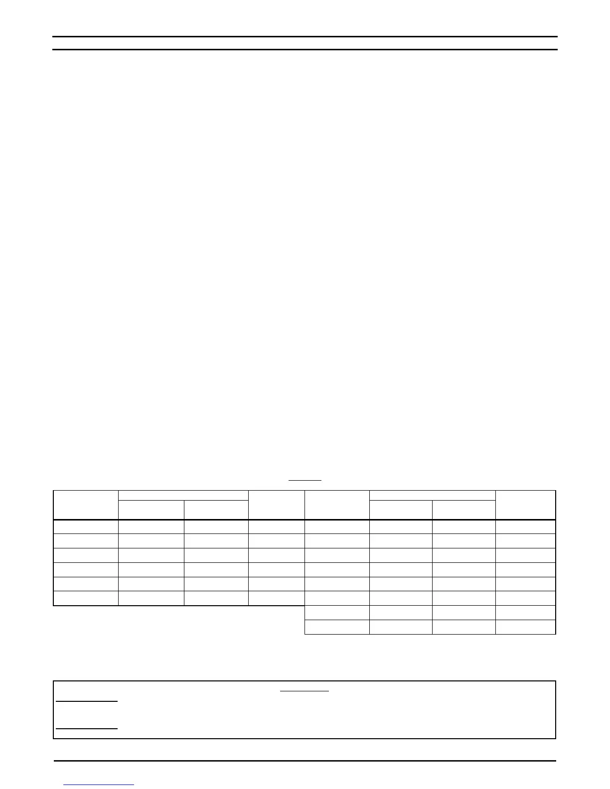
TABLE 1
DRIVE MODEL NO., PART NO., AND CASE REFERENCE SIZE
Model No.
Part No.
Case
Reference
Size Model No.
3
Part No.
Case
Reference
Size
Gray Case
(2G and 3G
2
)
White Case
1
(2G and 3G
2
) Gray Case White Case
1
KBAC-24D 9987 9988 A KBAC-217 8868 8879 C
KBAC-27D 9520 9521 B KBAC-217S 8863 8855 C
KBAC-29 9528 9529 B KBAC-217F 8861 8853 C
KBAC-29 (1P) 10001 10002 B KBAC-217SF 8869 8880 C
KBAC-45 9530 9531 B KBAC-416 8870 8881 C
KBAC-48 9540 9541 B KBAC-416S 8864 8856 C
KBAC-416F 8874 8883 C
KBAC-416SF 8871 8882 C
Notes: 1. White FDA approved finish. 2. Third Generation (3G) drives KBAC-24D, 27D, 29, 29 (1P), 45, 48 are marked "(3G)" on the product
label. Third Generation (3G) drives are jumper selectable (J12) for standard and sensitive GFCIs. 3. All KBAC-217, 416 Series drives are
Third Generation (3G).
UL NOTICE
230 Volt Drives: Suitable for use on a circuit capable of delivering not more than 5 kA RMS symmetrical Amperes. 230 Volts maximum.
Use copper conductors rated 75 °C. Suitable for operation in a maximum surrounding air temperature of 40 °C.
460 Volt Drives: Suitable for use on a circuit capable of delivering not more than 5 kA RMS symmetrical Amperes. 460 Volts maximum.
Use copper conductors rated 75 °C. Suitable for operation in a maximum surrounding air temperature of 40 °C.