13
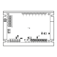
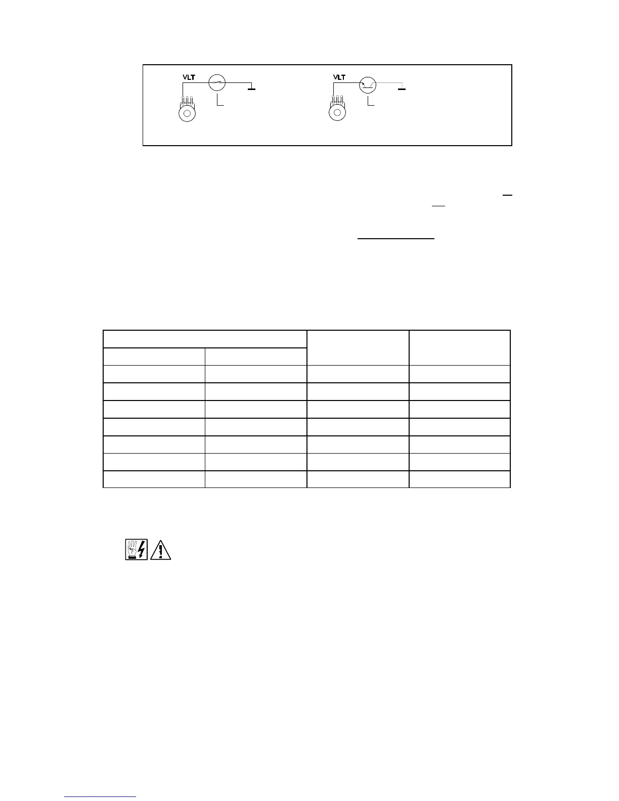
FIG. 15 – ENABLE CIRCUIT
V. FUSING.
A. AC Line Fusing – Most electrical codes require that each ungrounded conductor contain
fusing. Separate branch circuit fusing, or circuit breaker may be required. Check all
electrical codes that may apply to the installation. This control does not contain AC line
fuses. A 20 amp rated fuse or circuit breaker can be used.
B. Armature Fusing – The correct size armature fuse must be installed, depending on the
rating of the motor. Control will not operate if fuse is not installed. Fuse type should
be Littelfuse 326 ceramic, Buss ABC, or equivalent. A fuse chart is presented below
which suggests appropriate armature fuse ratings. However, the specific application may
require larger fuse ratings based on ambient temperature, CL set point and duty cycle of
operation. (See table 10 below.) (Fuse rating is based upon 1.7 times the motor current
rating.)
TABLE 10 – ARMATURE FUSE CHART
Motor Horsepower
Approx. DC Motor
Current Amps
Fuse Rating
(AC Amps)
90VDC 180VDC
1/8 1/4 1.3 2
1/6 1/3 1.7 2
1/4 1/2 2.5 4
1/3 3/4 3.3 5
1/2 1 5.0 8
3/4 1 7.5 12
1 2 10.0 20
Note: Armature fuse is not supplied and must be installed for control to operate.
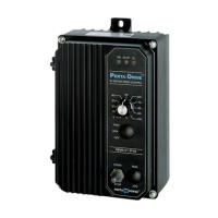
VI. OPERATION
WARNING! Read Safety Warning on page 2 before attempting to operate the
control or severe injury or death can result. Failure to follow the Safety
Warning Instructions may result in electric shock, fire or explosion.
After the control has been set up properly (the jumpers set to the desired positions, and the
wiring completed), the start-up procedure can begin. If AC power has been properly brought
to the control, the "ON" LED and the "STOP" LED indicators will be lighted. Before initially
starting, be sure the main potentiometer is in the minimum position. To start the control move
the Start/Stop toggle to the "Start" position and release. The "Stop" LED should extinguish
and the motor should rotate as the potentiometer knob is rotated clockwise. Note: If the
motor rotates in the incorrect direction, it will be necessary to disconnect the main AC power
and reverse the armature wires. To stop the motor, move the Start/Stop toggle to the Stop
position. If power is lost, the control will not restart, unless the Start/Stop toggle is moved to
the Start position.
SWITCH, RELAY OR FET
OPEN TO "STOP"
CLOSE TO "START
MAIN
POTENTIOMETER
MAIN
POTENTIOMETER
A SOLID STATE RELAY CAN ALSO
BE USED WITH OPEN COLLECTOR
P3 P3