i. Current Signal Input
Warning! Read Safety Warning on Page 1
before attempting to use this control.
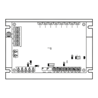
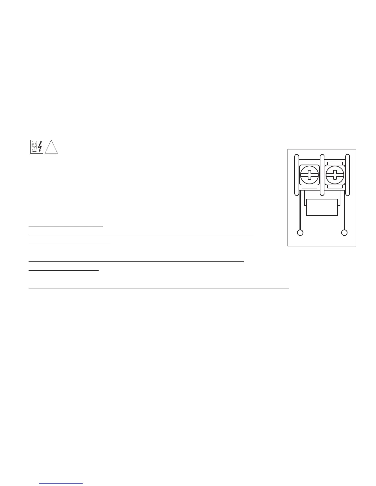
The Signal Isolator accepts 4 – 20 mA DC input to provide 0 – 9 Volts DC
output. Connect the current signal input common (–) to Terminal “5” and the
positive (+) to Terminal “6”, as shown in Figure 3. Other current signal input
ranges can also be used, as described below. Calibrate the Signal Isolator,
as described below.
Note: Two resistors, for 10 – 50 mA and 1 – 5 mA inputs, are supplied in
the hardware bag included with this kit.
4 – 20 DC Signal Input
: No resistor required. Set Jumper J1 in “CUR” position.
10 – 50 mA DC Signal Input (Use Large Resistor with Color Code
“Brown–Green–Brown”): Install the 150Ω – 1W resistor across Terminals.
“5” and “6”. Set Jumper J1 in “CUR” position.
1 – 5 mA DC Signal Input (Use Small Resistor with Color Code
“Brown–Black–Red”): Install the 1kΩ – 1/4W resistor across Terminals “5” and “6”. Set Jumper J1
in “VOLT” position.
Procedure to Calibrate the Signal Isolator When Using Current Signal Input
:
1. Connect a DC voltmeter (a digital voltmeter is suggested) to Terminals “9” (–) and “10” (+).
2. Apply the minimum signal input current to Terminals “5” (–) and “6” (+).
3. Adjust the MIN Trimpot on the Signal Isolator to obtain an output voltage of 0 Volts DC.
4. Apply the maximum signal input current to Terminals “5” (–) and “6” (+).
5. Adjust the MAX Trimpot on the Signal Isolator to obtain an output voltage of 9 Volts DC.
Notes: 1. To achieve better accuracy, repeat steps 2 – 5. 2. If other than 0 Volts DC (minimum) and 9
Volts DC (maximum) is desired, use the MIN and MAX Trimpots on the Signal Isolator to adjust the
output to the desired voltages in steps 3 and 5.
6