ii. Voltage Input Signal
Warning! Read Safety Warning on Page 1
before attempting to use this control.
Note: The Voltage/Current (VLT/CUR) jumper must be in the VLT position (factory setting).
The KBSI-240D is designed to accept a wide range of input voltage signals as follows:
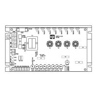
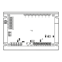
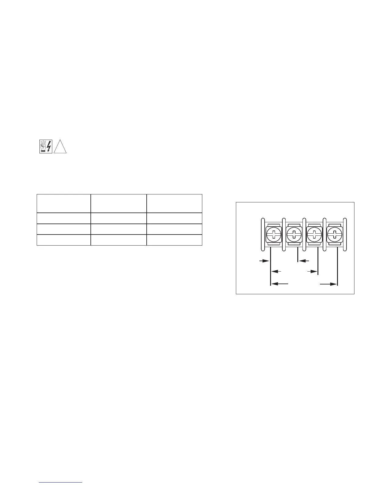
Connect input voltage signal to proper input terminals as
indicated in figure 4.
1. Connect a 10V DC meter (digital meter is suggested)
to terminals “9” (-) and “10” (+).
2. Apply the maximum input voltage that would be supplied from tach, transducer, etc.
3. Adjust the “MAX” trimpot to the desired output voltage.
Example: A follower motor is to follow the output of a main motor with an armature volt-
age range of 0 - 90V.
7
Minimum Input
Voltage Range
Input Terminals
5, 6
Maximum Input
Voltage Range
0 - 5 0 - 25
5, 7 0 - 25 0 - 120
5, 8 0 - 120 0 - 550
TABLE 2 – VOLTAGE INPUT SIGNAL