© Copyright 2016 KE2 Therm Solutions, Inc., Washington, Missouri 63090
Q.3.20 (Q.1.20) October 2016
Page 2
KE2 Temp + Defrost (pn 20611)
For Medium Temperature Applications with Air Defrost
Installation Manual
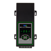
When wiring the controller rst remove the display by loosening the
four corner screws. The display is connected to the lower board by a
short ribbon cable.
Caution: The board may be damaged if excessive force is used when
removing the cover.
1
Wiring the Controller
The KE2 Temp was designed with simplicity in mind. The controller
accepts 120V / 208-240V to power the controller and 12V - 240V sole-
noid voltage via the liquid line solenoid relay through the lower con-
duit connection. The temperature sensor and communication wires
are attached via the upper conduit connector.
After the four screws have been detached from the lower section, the
cover may be gently moved to the side.
2
Next remove the high voltage protective cover. There are two screws
holding it in place.
3
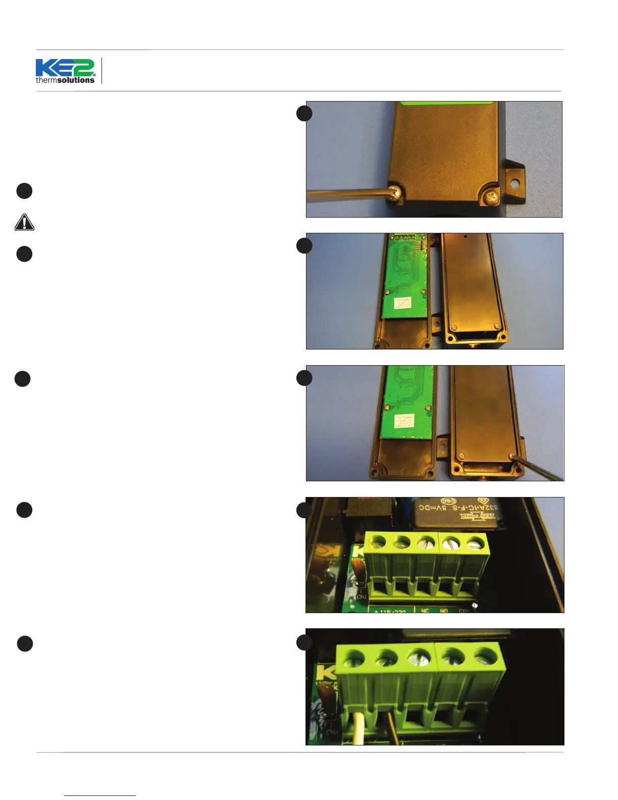
With the high voltage cover removed, the two screw terminal con-
nectors can be seen. The 2-position connector is the controller’s
power supply. The voltage selector switch should be positioned to
match the voltage supplied.
4
1
2
3
4
5
5
Connect line (L1) to the right terminal position and neutral (L2) to the
left terminal position.

 Loading...