GB-10
12345
6789
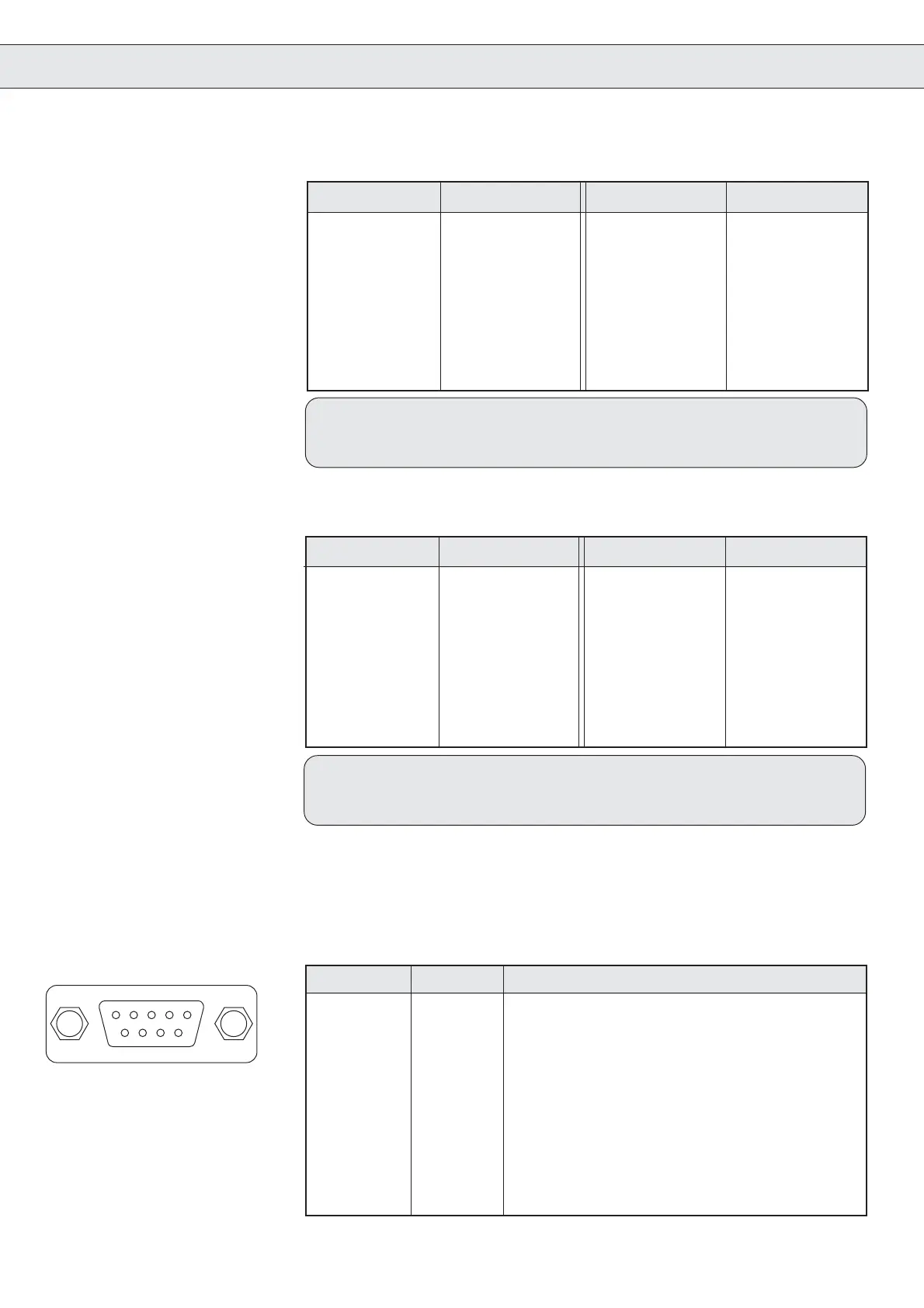
PIN-No. Signal Meaning
1 A + Signal Channel A
2 B + Signal Channel B
3 reserved
4 + 5 V Voltage output
5 + 24 V external voltage supply
6 A- inverted signal channel A
7 B- inverted signal channel B
8 reserved
9 GND external ground
Housing Shielding
2.4 Connection X5
Incremental Encoder
Emulation
The 9-pole sub-d-socket is used as an incremental encoder output.
The signals are emitted corresponding to the signals on the incremental
encoder input X4 in RS422 specifications.
Encoder 2
Connection
PIN-No. Signal PIN-No. Signal
1 9 SIN+
2 10 12 V
3 REF_COS 11
4 REF_SIN 12
5 13 GND
6 14 DATA-
7 15 DATA+
8 COS+ Housing Shield
2.3.4Connection
Hiperface Encoder
PIN-No. Signal PIN-No. Signal
1U- 9B+
2V- 10W+
3 A- 11 15 V
4B- 125 V
5 W- 13 GND
6U+ 14N-
7V+ 15N+
8 A+ Housing Shield
2.3.5Connection UVW
Encoder
The connector may only be connected / disconnected when
the inverter and voltage supply are shut off.
The connector may only be connected / disconnected when the
inverter and voltage supply are shut off.
 Loading...

