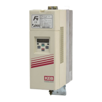
Do you have a question about the KEB COMBIVERT F4-F and is the answer not in the manual?
| Category | Lifting Systems |
|---|---|
| Series | COMBIVERT F4-F |
| Braking Transistor | Integrated |
| Enclosure Rating | IP20 |
| Control Method | Sensorless Vector Control |
| Safety | STO (Safe Torque Off) |
| Communication | CANopen, PROFIBUS |
| Protection Features | Overcurrent, Overvoltage, Undervoltage, Overtemperature, Short Circuit |
| Relative Humidity | < 95% (non-condensing) |
The frequency inverter KEB COMBIVERT F4-F Lift Version 1.4 is specified for lift technology.
Connections of terminal strip and encoder inputs are safely isolated in accordance with VDE 0100.
Measures to reduce interference pulses from the frequency inverter affecting electric systems.
Measures for operational reliability and additional protection against malfunctions.
Details the function, voltage, and current specifications for each terminal on X2.
Details the function, voltage, and current specifications for each terminal on X3.
Explains the operation and logic of the inverter's digital inputs.
Explains the operation of digital inputs X2.5-X2.7 and X3.1-X3.7.
Explains the operation of digital and relay outputs.
Explains the operation of digital outputs X3.14-X3.23.
Diagram showing speed over time with associated input/output signals for main drive activation.
Detailed description of operating points for the main drive sequence.
Explains how to activate the door drive using input X2.6.
Diagram showing speed over time with associated input signals for door drive.
Reduces operating frequency based on heat sink temperature to prevent overheating.
Describes the function of output X3.14 as an operating frequency warning.
Diagram showing connections between control terminal X2 and I/O-Expander X3.
Details pin assignment and input wiring for connecting an incremental encoder.
Details pin assignment and output signals for SIN/COS encoder.
Details pin assignment and signals for connecting a resolver.
Explains the use of the 9-pole sub-D socket for incremental encoder output.
Describes the necessity and availability of operators for local inverter operation.
Explains how to identify and display parameter groups and numbers.
Illustrates selecting parameter groups and numbers using operator keys.
Shows how to increase/decrease parameter values and display identification.
Outlines parameter groups (LF, ru, In) and their types.
Explains how to transfer and permanently store adjusted parameter values.
Describes how to display and reset error messages.
Details parameters related to password, steering, and operating modes.
Explains digital setpoint input functions for Steering/Operating Mode (LF.02).
Describes parameters LF.3, LF.4, and LF.5 for encoder output, motor selection, and direction.
Details parameters LF.10 to LF.16 for ASM motor specifications.
Details parameters LF.17 to LF.20 for encoder and speed settings.
Details parameters LF.21 to LF.28 for mechanical dimensions and door drive.
Details parameters LF.30 to LF.32 for control method and speed controller gains.
Details parameters LF.33 to LF.37 for current control and torque limits.
Details parameters LF.38 and LF.40 to LF.43 for frequency and speed settings.
Details parameters LF.44, LF.45, LF.46, LF.50 for intermediate speeds, door speed, jerk.
Details parameters LF.51 to LF.54, LF.60 for acceleration, deceleration, brake.
Details parameters LF.61 to LF.66 for overspeed, voltage, temperature.
Details parameters LF.67 to LF.70 for pretorque and brake release.
Details parameters LF.71 to LF.74 for crawl path optimization.
Details parameter LF.75 for the Ogive Function.
Details parameter LF.76 for Ogive Status and special cases.
Details parameters LF.77 and LF.78 for braking distance and floor height.
Details parameters LF.80 to LF.83 for software version and terminal states.
Details parameters LF.84 to LF.88 for terminal states and actual speed.
Details parameters LF.89 to LF.92, LF.98, LF.99 for speed, torque, positioning, errors, states.
Lists and describes fault messages with their corresponding error codes.
Details parameters LF.A0 to LF.A8 for SSM Rated Motor parameters.
Details parameters LF.b0 to LF.b2 for SSM Encoder and system position.
Details parameters LF.b3, LF.b4, LF.b5 for speed scan, error trimming, system position.
Details parameters LF.C0 to LF.C5 for SSM speed and current control.
Displays inverter operating conditions.
Details ru-parameters for current, voltage, terminal status.
Details ru-parameters for speed reference, analog voltage, OL counter.
Details ru-parameters for power on and modulation on counters.
Presents inverter data: type display, rated current.
Details In-parameters for serial numbers, customer numbers, error counters.
Details In-parameters for error counters, software ID, date, feedback.
Flowchart for initial start-up with asynchronous motor.
Flowchart for initial start-up with synchronous motor.
Guidance for adjusting conventional lift motors with missing data.
Lists new features introduced in version 1.4 of the inverter software.
Wiring diagram for control instructions and safety circuits.
Comprehensive table listing parameters, addresses, ranges, defaults.
Continues the comprehensive parameter list.
Continues the comprehensive parameter list.
Lists parameters for customer adjustment with size, unit.