GB 6
GB
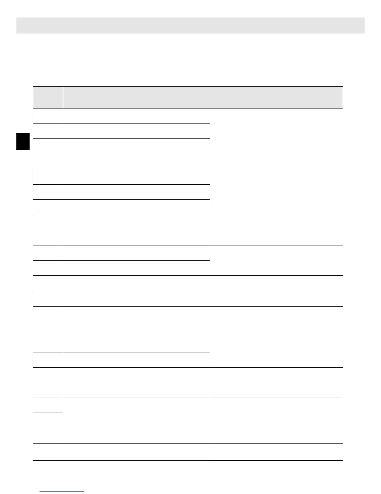
3. Inputs/Outputs
3.1 Terminal X2
Control Terminals
Terminal Function
1 Control Release
2 Reset digital inputs:
3 Direction of travel forward noise immunity: 2 kV
4 Direction of travel reverse logic 1: ± 12…30 V
5 Control Mode internal input resistor: approx. 2 kΩ
6 Door drive active PNP-logic
7 Door drive setpoint input
8 Digital output signal: braking control see page E 10
9 Digital output signal: main protection control inverted see page E 10
10 + 18 V voltage output +18V (+/- 20%) ; max. 20 mA
! When external voltage is connected to
11 Ground for X2.10 and digital inputs/outputs terminal X2.23 then U
X2.10
≈≈
≈≈
≈ U
X2.23
!
12 +10 V reference voltage
+10V (+/- 3%) ; max. 6 mA
13 Ground for analog inputs/outputs
14 Differential voltage input / resolution: 12 Bit
Analog setpoint input (see parameter LF.2) Ri = 40 kΩ
15 Smoothing time: 2 ms / processing time: 1...3 ms
16 Analog input of the precontrol torque
(see parameter LF.30 and LF.67)
17
Option ! do not connect !
18 Analog output set speed -10V…+10V / resolution: 8 Bit Ri = 100 Ω
conditional short-circuit proof( <1 min )
19 Analog output actual speed 0...10V = 0...2 x synchronous speed
20
30 VDC / 1 A
21 Relay control cabinet fan control (LF.66)
see page E 17
22
23 External voltage supply + 24 ... + 30 V external voltage input
for digital outputs on terminal strip X2
^

 Loading...
