15
TROUBLESHOOTING
This unit has on - board diagnostics. Error codes appear on the LED display on the front panel of the indoor unit in place of the temperature
display. Error codes are also displayed on the outdoor unit microprocessor board with colored LED lights. The table below explains the error
codes for both units.
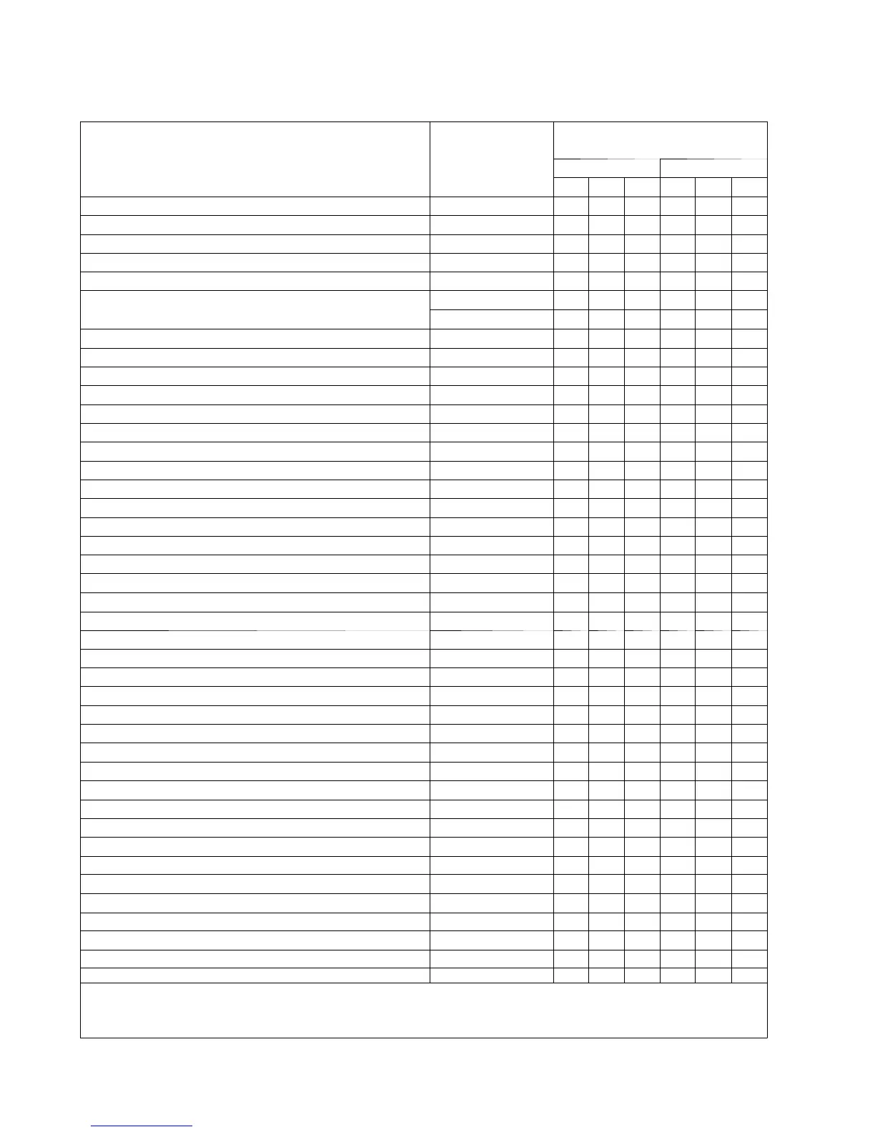
Table 16—Diagnostic Codes
Malfunction Display of
indoor unit
Display of lamp (the times of blinking)
Indoor Outdoor
R C H Y R G
Anti-freezing protection E2 2 3
Block or Low pressure of refrigerant system E3 3 9
Compressor exhaust high temperature protection E4 4 7
AC over-current protection E5 5 5
Communication failure between indoor unit and outdoor unit E6 6 O/U
Anti-high temperature protection
E8 8 6
H4 4 6
No feedback of indoor fan motor H6 11
Jumper cap malfunction protection C5 15
Indoor unit and outdoor unit doesn't match LP 19 16
Outdoor DC fan motor malfunction L3 23 14
Power protection L9 20 9
Gathering refrigerant Fo 1 1
Indoor ambient sensor open or short circuit F1 1
Indoor tube sensor open or short circuit F2 2
Outdoor ambient sensor open or short circuit F3 3 6
Outdoor tube sensor open or short circuit F4 4 5
Exhaust sensor open or short circuit F5 5 7
Overload limit / drop frequency F6 6 3
Over current limit / drop frequency F8 8 1
High exhaust temperature limit / drop frequency F9 9 2
Refrigerant leakage protection F0 10 9
Anti-freezing limit / drop frequency FH 2 2 4
Defrosting H1 1 2
Compressor overload protection H3 3 8
IPM protection H5 5 4
Module temperature is too high H5 5 10
PFC protection HC 6 14
Loading EEPROM malfunction EE 15 11
High PN voltage protection PH 11 13
Low PN voltage protection PL 21 12
4-way valve reversal abnormal U7 20
DRED1 / DRED2 / DRED3 d1/d2/d3
Compressor Min frequence in test state P0
Compressor rated frequence in test state P1
Compressor maximum frequence in test state P2
Compressor intermediate frequence in test state P3
Compressor is running(normal) 1
The temperature for turning on the unit is reached (normal) 8
Frequency limiting (module temperature) EU 6 6 11
Frequency limiting (power) LU 24 13
Notes: R(Indoor)--Running C--Cooling H--Heating Y--Yellow R(Outdoor)--Red G--Green
O/U--OFF or Unblink The display difference between Fo and F0 is 'o' is the bottom part of figure 8