F96VTN and G96VTN: Installation, Start-up, Operating and Service and Maintenance Instructions
Manufacturer reserves the right to change, at any time, specifications and designs without notice and without obligations.
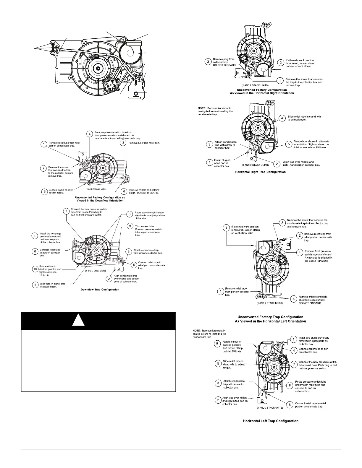
11
A11307
Fig. 8 – Upflow Trap Configuration
(Appearance may vary)
A11587
Fig. 9 – Downflow Trap Configuration
(Appearance may vary)
A11573
Fig. 10 – Horizontal Right Trap Configuration
(Appearance may vary)
A11574
Fig. 11 – Horizontal Left Configuration
(Appearance may vary)
NOTICE
!
The field-supplied, accessory horizontal drain trap grommet is ONLY
REQUIRED FOR DIRECT VENT APPLICATIONS. It it NOT
required for applications using single-pipe or ventilated combustion air
venting.
The condensate trap extends below the side of the casing in the
horizontal position. A minimum of 2-in. (51 mm) of clearance is
required between the casing side and the furnace platform for the trap to
extend out of the casing in the horizontal position. Allow at least 1/4-in.
per foot (20 mm per meter) of slope down.
Condensate Trap
Relief Port
Collector Box
Plugs
Pressure Switch
Port
Condensate Trap
Outlet
Condensate Trap
Relief Port
Collector Box
Plug
Vent Elbow
Vent Elbow Clamp
Vent Pipe Clamp
UPFLOW TRAP CONFIGURATION
1 & 2 Stage Units