18
(c) If the condenser is installed more than 5 ft (1.52 m) higher than the outlet drain point of the condenser, a
vacuum breaker or open vent line should be provided to prevent the outlet line from creating a partial
vacuum condition.
CONSULT THE FACTORY OR LOCAL SALES REPRESENTIVE FOR FURTHER INFORMATION.
90
o
F 100
o
F 110
o
F 90
o
F 100
o
F 110
o
F
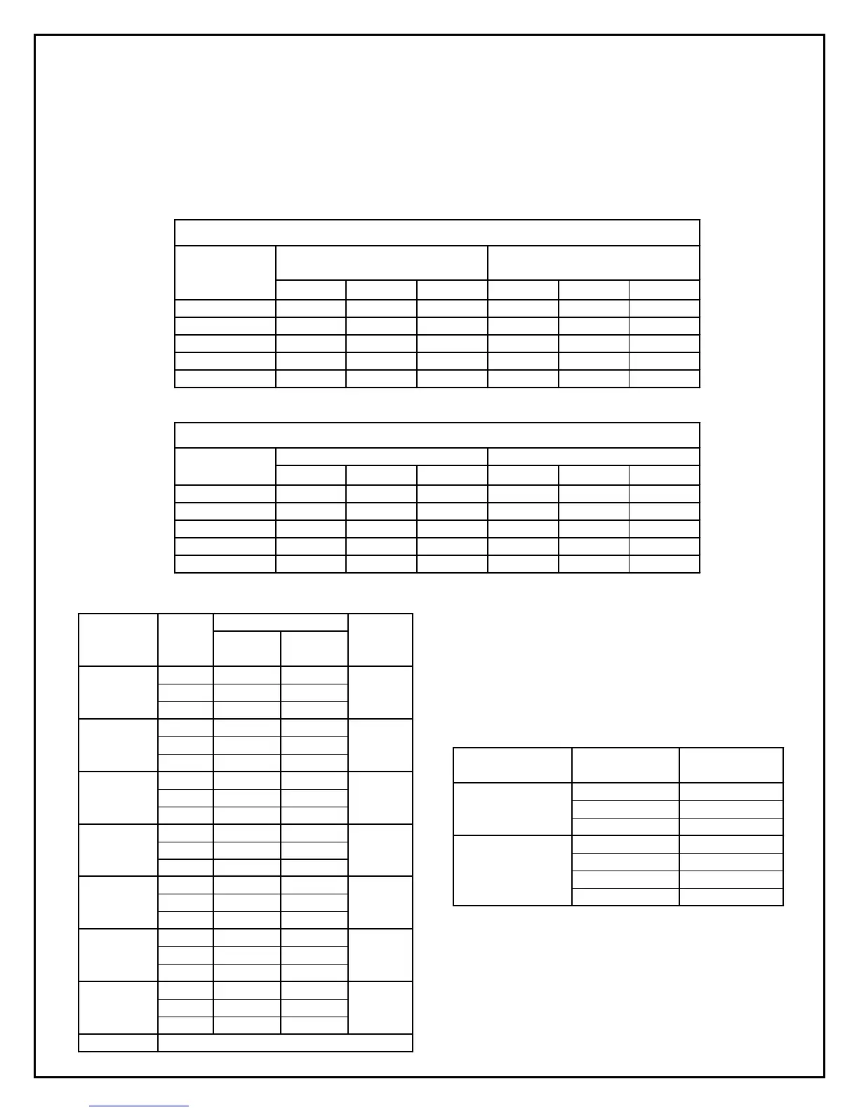
45
0.135 0.137 0.142 0.168 0.172 0.175
25
0.144 0.148 0.153 0.179 0.185 0.189
15
0.148 0.153 0.158 0.185 0.192 0.197
-10
0.167 0.173 0.182 0.208 0.217 0.225
-30
0.183 0.190 0.200 0.227 0.237 0.250
90
o
F 100
o
F 110
o
F 90
o
F 100
o
F 110
o
F
45
0.092 0.093 0.095 0.113 0.115 0.118
25
0.097 0.100 0.103 0.121 0.125 0.128
15
0.100 0.103 0.107 0.125 0.130 0.133
-10
0.113 0.118 0.123 0.142 0.147 0.153
-30
0.123 0.128 0.135 0.153 0.160 0.168
Evaporating
Temperature
SERIES PARALLEL
WATER FLOW REQUIREMENTS
(Gallon Per Minute Per 1 MBH Evaporator Load)
LOWER WATER FLOW RATES
30
o
TD
(Condensing Temperature - Entering Water Temperature)
PARALLEL
Condensing Temperature
Evaporating
Temperature
20
o
TD
(Condensing Temperature - Entering Water Temperature)
HIGHER WATER FLOW RATES
SERIES
Condensing Temperature
10.6
22
34.2
22.40.3
48.71.2
6 18.6 2.5
22.70.4
49.91.4
6212.9
32.70.4
57.2 1
9212.9
5 2.6 0.35
10 9 1.25
15 18 2.7
10 0.7
15 1.4
25 3.4
10 0.4
20 1.3
40 4.6
30, 35, 40
Typical Pressure Drops (PSIG) Condensers
Consult factory for Data
1
1
3/4
1/2
10
15
20, 25
1 1/2
1 1/4
1 1/4
1,1 1/2 , 2
3, 3 1/2, 4
5, 6
7 1/2, 9
Water
Valve
Size
Flow
(GPM)
Model (HP)
Pressure Drop
Series Parallel
11.7
26.2
3 13.5
10.5
21.3
32.8
45.9
Larger compressor models use fans in place of water cooling coils.
Compressor Coil (smaller models only)
T
ical Pressure Dro
s
PSIG
Compressor
Model Family
Flow (GPM) Pressure Drop
KW
EW / 3W