Step 1: Unwrap the pedal set and Loctite 242,
obtain the Torque wrench, 15mm crowfoot, 4”
extension, and 15mm open-end wrench.
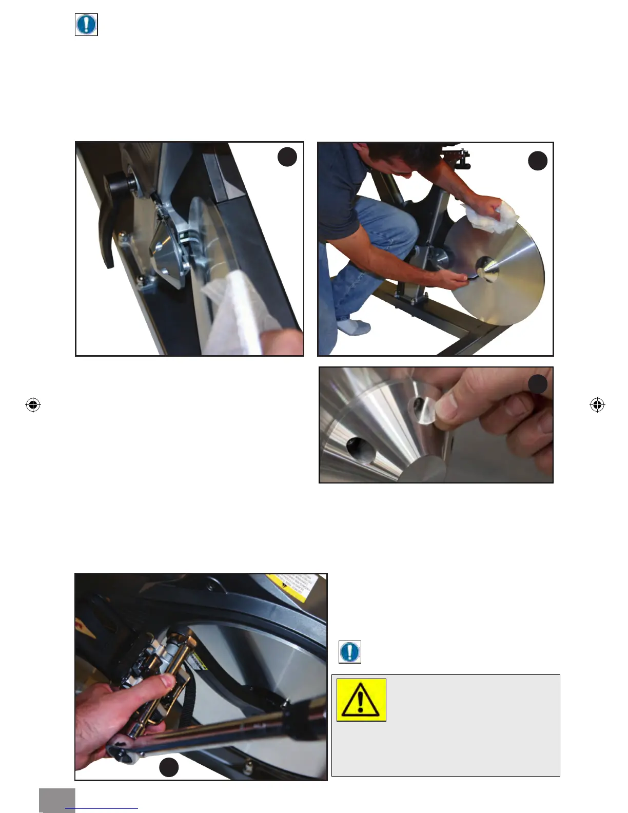
NOTE: Use the foam envelope to handle the ywheel during assembly.
Step 3: Carefully slide the ywheel between the two magnets (Fig 4. & Fig. 5) and onto the
hub at the same time. Make sure that the ywheel is ush against the hub and align the
screw holes.
Step 4: Holding the ywheel in position with one hand, install the hubcap and align the
screw holes. Install the socket head cap screws (M6x1 X 20 SS). Using the 5mm Allen
wrench, tighten the screws in a star pattern until snug (as shown in Fig. 6).
Step 5: After 5 hub screws have been
installed, apply 5 clear decals to each side of
the hub cover as shown (Fig. 6a).
5
6
WARNING!
Failing to install the pedals with Loctite 242,
or crossing the threads will damage them,
and could result in serious injury to the user.
7
NOTE: Left pedal is LH threads
and right pedal is RH threads.
Step 2: With a clean cloth, wipe the
threaded area of the pedals. Apply
Loctite 242 to the pedal threads. Install
the pedals into the crank arms, use the
15mm open-end wrench to tighten.
Finish with the torque wrench, 15mm
crowfoot, and 4” extension. Torque
pedals to 45 Nm (35 ft-lbs) (Fig. 7).
ASSEMBLING PEDAL TO CRANK ARM
6a
5