nent in the high impedance circuitry, or if the high impe-
dance circuitry (InA-1rA range resistors) are contaminated,
use the following procedure to clean the circuit:
1. Clean the entire high impedance circuit with methanol
and a clean cotton swab.
2. Blow dry the circuit with dry nitrogen gas.
3. Inspect the circuit for any residue fcontamination) and
repeat steps 1 and 2 if any residue is found.
4. Reassemble taking care not to touch the clean com-
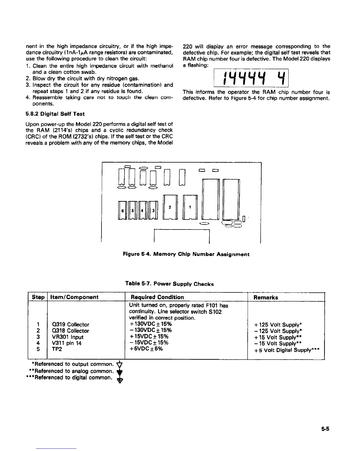
220 will display an errrx message corresponding to the
defective chip. For example; the digital self test reveals that
RAM chip number four is defective. The Model 220 displays
a flashing:
jl
This informs the operator the RAM chip number four is
defective. Refer to Figure 5-4 for chip number assignment.
5.8.2 Digital Self Test
Upon power-up the Model 220 performs a digital self test of
the RAM (2114’s) chips and a cyclic redundancy check
(CRC) of the ROM (2732’s) chips. If the self test or the CRC
reveals a problem with any of the memory chips, the Model
a319 Collector
Q318 Collector
Figure 5-4. Memory Chip Number Assignment
-
-
Table 5-7. Power SUpply Checks
Required Condition
Unit turned on, properly rated FlOl has
continuity. Line selector switch S102
verified in correct position.
+ 130VDC f 15%
- 130VDC f 15%
+15VDC+15%
-15VDC?15%
+5VDC+5%
Remarks
+ 125 Volt Supply”
- 125 Volt Supply’
+ 15 Volt Supply””
- 15 Volt Supply**
+ 5 Volt Digital Supply’“*
I I
I
*Referenced to output common. ‘i)
“Referenced to analog common. *
‘*‘Referenced to digital common. $
5-5