2: Front-panel overview Model 2470 High Voltage SourceMeter Instrument
2-4 2470-900-01 Rev. A / May 2019
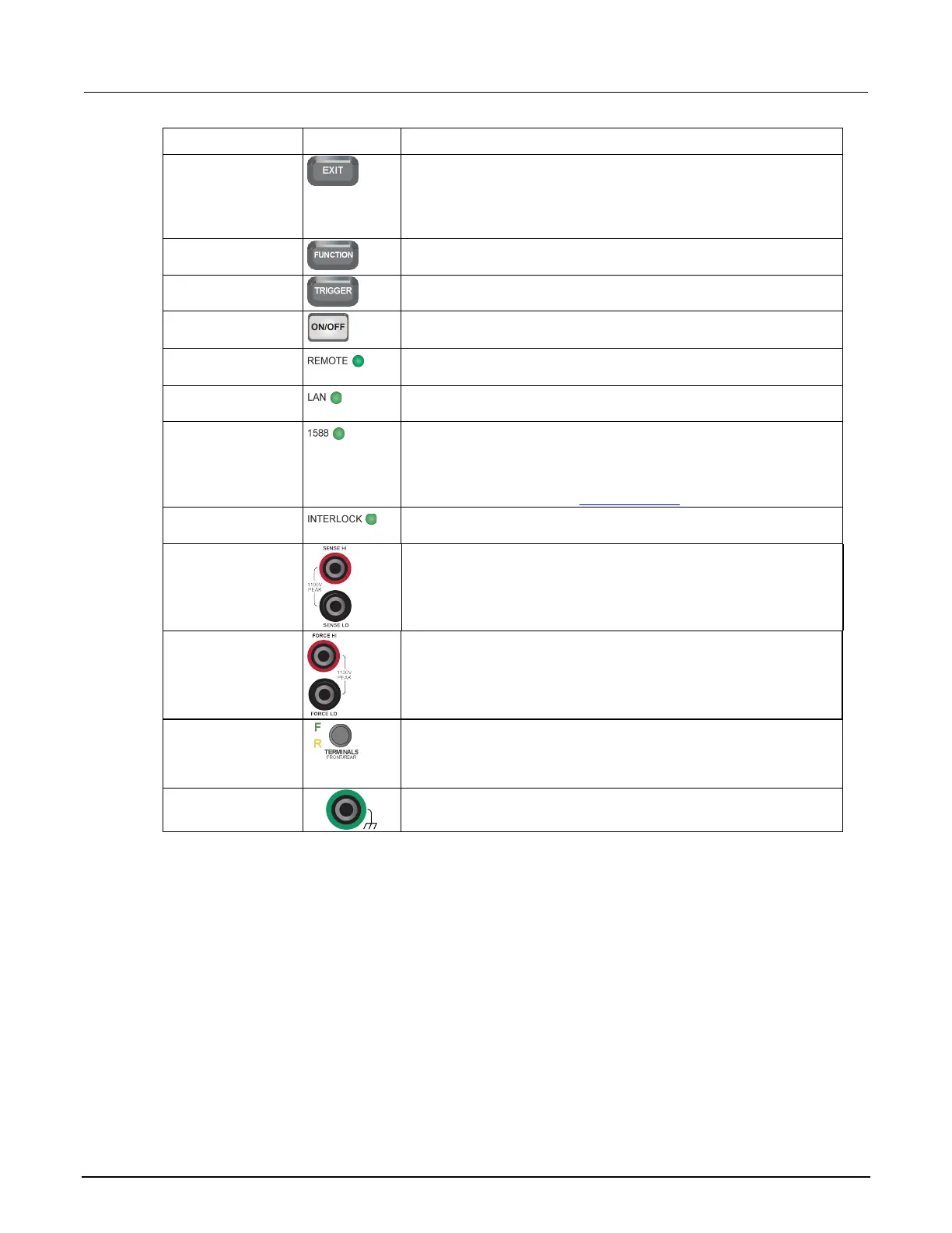
Control Graphic Description
EXIT key
Returns to the previous screen or closes a dialog box. For example,
press the EXIT key when the main menu is displayed to return to the
home screen. When you are viewing a subscreen (for example, the
Event Log screen), press the EXIT key to return to the main menu
Displays instrument functions. To select a function, touch the function
name on the screen.
Accesses trigger-related settings and operations. The action of the
TRIGGER key depends on the instrument state.
OUTPUT ON/OFF
Turns the output source on or off. The switch illuminates when the
source output is on.
indicator
Illuminates when the instrument is controlled through a remote
interface.
Illuminates when the instrument is connected to a local area network
(LAN).
1588 LED indicator
Illuminates when the instrument is connected to an IEEE-1588
compliant device.
Note that 1588 functionality is not supported at this time. This
functionality will be made available with a firmware update. See the
2470 Release Notes on the tek.com/keithley for details.
Illuminates when the interlock is enabled.
Use the SENSE HI and SENSE LO terminal connections to measure
voltage at the device under test (DUT). When you use sense leads,
measurement of the voltage drop across the force leads is eliminated.
This produces more accurate voltage sourcing and measurement at
the DUT.
Use FORCE HI and FORCE LO terminal connections to source or
sink voltage or current to or from a device under test (DUT).
TERMINALS switch
Activates the terminals on the front or rear panel. When the
front-panel terminals are active, a green "F" is visible to the left of the
FRONT/REAR switch. When the rear-panel terminals are active, a
yellow "R" is visible to the left of the switch.
Banana jack connector that provides a chassis connection.