System SourceMeter® Instrument Reference Manual Section 2:
2600BS-901-01 Rev. B / May 2013 2-57
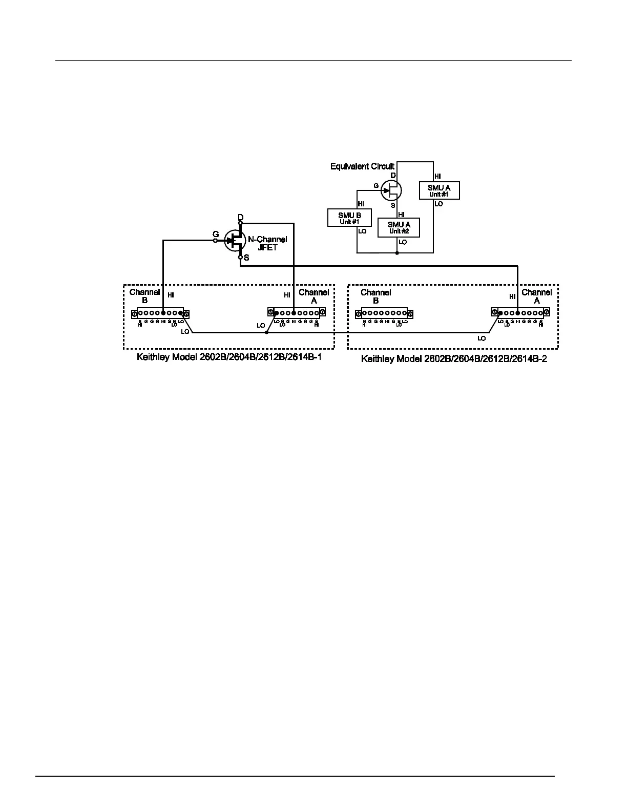
The following figure illustrates using three SMUs to test the same 3-terminal device. The third SMU is
connected to the source (S) terminal of the JFET. This allows the source terminal to be biased above
signal LO. Setting this SMU to output 0 V effectively connects the source terminal of the JFET to
signal LO.
Figure 24: Three SMUs connected to a 3-terminal device
 Loading...