2600S-901-01 Rev. C / January 2008 Return to Section Topics 8-11
Series 2600 System SourceMeter® Instruments Reference Manual Section 8: Source-Measure Concepts
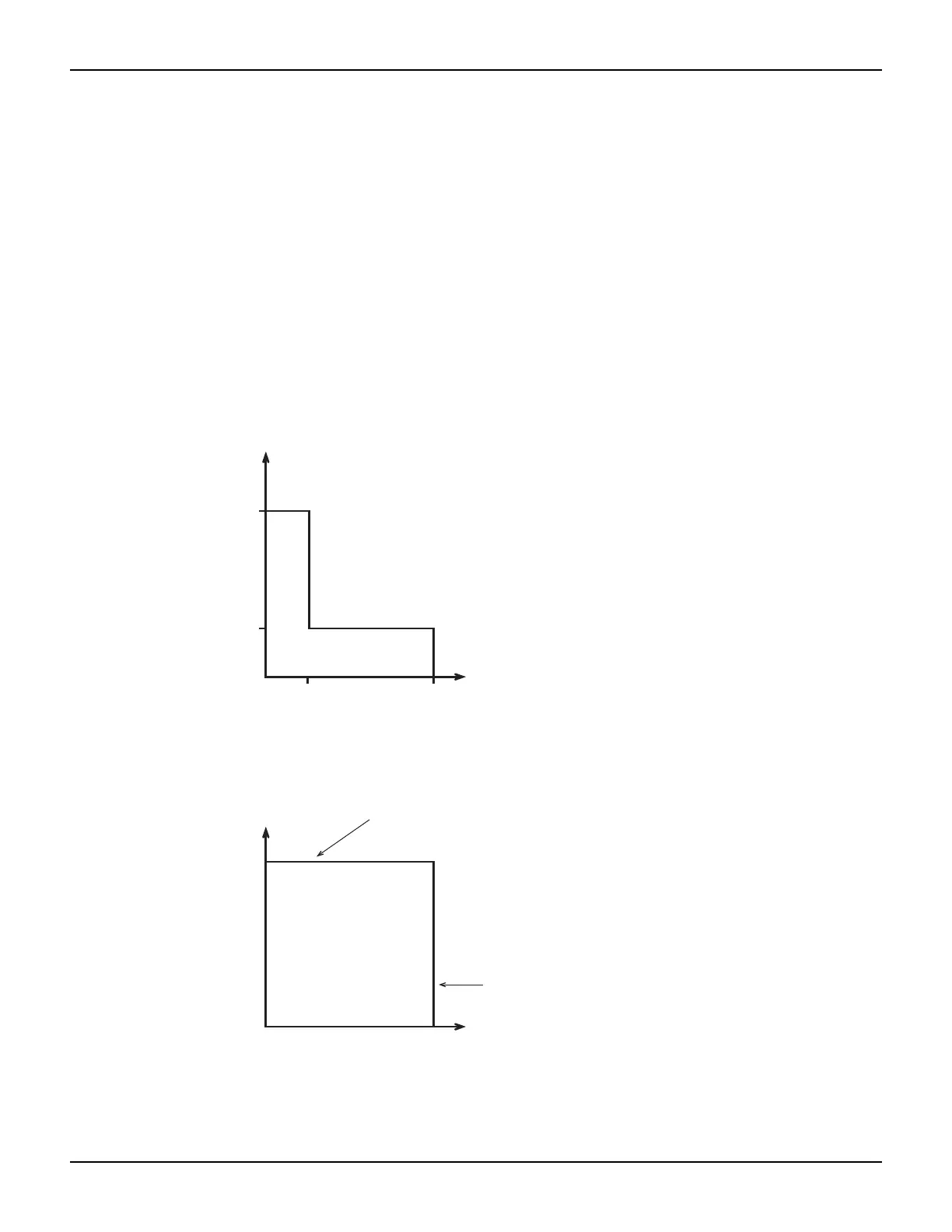
Model 2611/2612/2635/2636 I-Source operating boundaries
Figure 8-6 shows the operating boundaries for the I-Source. Only the first quadrant of operation is
covered. Operation in the other three quadrants is similar.
Figure 8-6A shows the output characteristics for the I-Source. As shown, the Model 2611/2612/
2635/2636 SourceMeter can output up to 101mA at 200V, or 1.515A at 20V. Note that when
sourcing more than 101mA, voltage is limited to 20V.
Figure 8-6B shows the limit lines for the I-Source. The current source limit line represents the
maximum source value possible for the presently selected current source range. The voltage
compliance limit line represents the actual compliance that is in effect. See “
"Compliance limit"”
earlier in this section. These limit lines are boundaries that represent the operating limits of the
SourceMeter for this quadrant of operation. The operating point can be anywhere inside (or on)
these limit lines. The limit line boundaries for the other quadrants are similar.
Figure 8-6
Model 2611/2612/2635/2636 I-Source bo
Voltage
Compliance
Limit Line
Current Source
Limit Line
V Measure
200V
20V
101mA
1.515A
A) Output Characteristics
B) Limit Lines
I Source
Source I
Limit V
undaries
 Loading...


