Appendix A: Non-Kelvin (2W) S530 system diagnostics S530 Diagnostic Manual
NOTE
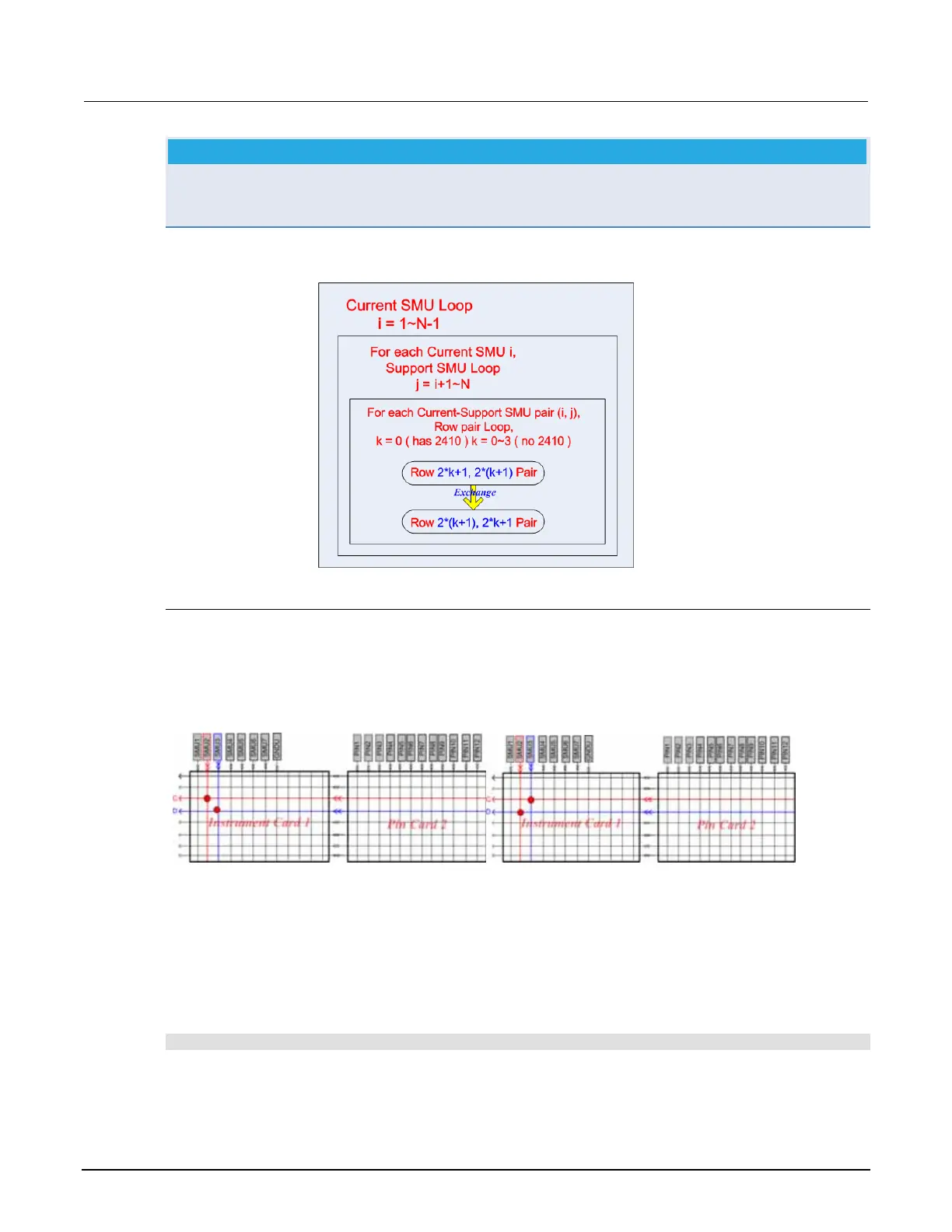
A loop is used to check between the two SMUs, but only row k and row k+1 (n = 1, 3, 5*) will be
arranged as a group and tested. The pair of rows will be tested in reverse order once to test the paths
opposite direction. For example, the row A and B test path will change to row B and A.
Figure 23: Current SMU loop
Basic short test connections
When two SMUs are working in 2W mode the basic test will only check the cross point on the
instrument card. For Example, the current SMU is SMU2, and the support SMU is SMU3, and the row
pair is (C, D)(see next Figure):
Figure 24: Test connections, rows C and D
Basic continuity test
The basic continuity test is executed by connecting two SMUs in the same row, forcing 1mA from the
first SMU, forcing 0V from the second, and then measuring the voltage and current with the first SMU.
If the resistance is higher than 2*1Ohm (determined by calculating the measured voltage and
current), Fail will display in the ACS GUI test log and in the diagnostic report in the following default
directory (see next Figure):
C:\ACS\Projects\Diagnostic\Reports
5. The N represents the number of SMUs. The loop should be SMU1 to SMU (N-1), because the
last SMU was tested by previous loops.
2-6 S530-906-01 Rev. A / March 2011
 Loading...


