2-1
Section 2
Two-terminal Device Tests
2.1 Introduction
Two-terminal device tests discussed in this section include voltage
coefficient tests on resistors, leakage tests on capacitors, and diode
characterization.
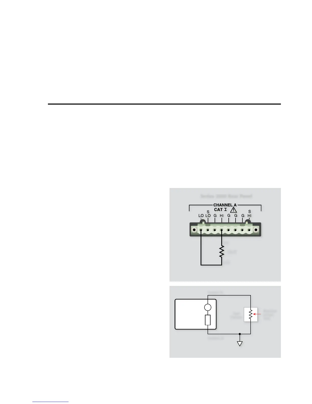
2.2 Instrument Connections
Figure 2-1 shows the instrument connections for two-terminal
device tests. Note that only one channel of a Source-Measure Unit
(SMU) is required for these applications. Be aware that multi-
channel models, such as the Model 2602, can be used, but are not
required to run the test program.
WARNING
Lethal voltages may be present. To avoid a possible
shock hazard, the test system should be equipped
with protective shielding and a safety interlock
circuit. For more information on interlock tech-
niques, see Section 10 of the Series 2600 Reference
manual.
Turn off all power before connecting or discon-
necting wires or cables.
NOTES
Remote sensing connections are recommended for optimum 1.
accuracy. See paragraph 1.2.2 for details.
If measurement noise is a problem, or for critical, low level 2.
applications, use shielded cable for all signal connections.
2.3 Voltage Coefficient
Tests of Resistors
Resistors often show a change in resistance with applied voltage
with high megohm resistors (>10
9
W) showing the most pro-
nounced effects. This change in resistance can be characterized as
the voltage coefficient. The following paragraphs discuss voltage
coefficient tests using a single-channel Model 2601 System Source-
Meter instrument. The testing can be performed using any of the
Series 2600 System SourceMeter instruments.
2.3.1 Test Configuration
The test configuration for voltage coefficient measurements is
shown in Figure 2-2. One SMU sources the voltage across the
resistor under test and measures the resulting current through
the resistor.
2.3.2 Voltage Coefficient Calculations
Two different current readings at two different voltage values are
required to calculate the voltage coefficient. Two resistance read-
 Loading...


