– 32 – – 33 –
Voltage and current measurement
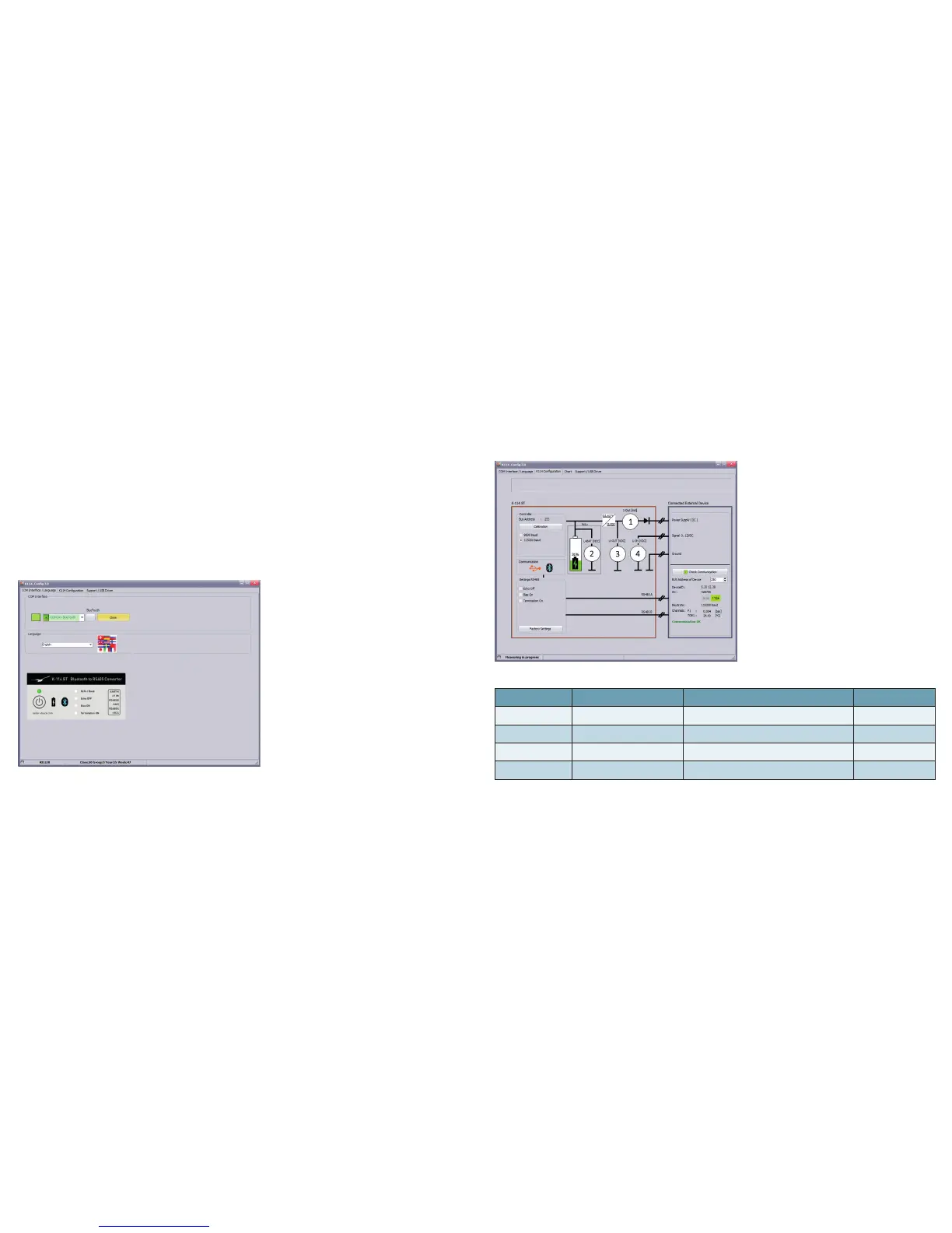
The latest conguration and measurements are continuously displayed and updated.
The RS485 connection to a connected device can be checked by pressing the button "Test communication".
No. Symbol Function Description
1 I-OUT Supply current to external consumers
Range 0…150 mA
2 U-BAT Voltage of the internal battery
3,1…4,2 V
3 U-OUT Supply voltage to external consumers
~ 15 V
4 U-IN Voltage input Range 0…12 VDC
Software K-114_Cong
The software K-114_Cong is a conguration and diagnostic tool for the converter K-114 BT. It can be used to
congure the baud rate of the converter, as well as to select the echo function and to switch on the bias resistors or
the termination resistor. If an end consumer is connected, a full diagnostic test can be run to determine the power
consumption and applied signal voltage and a communication test can be performed.
Installation
First, install the K-114 BT driver on your computer, then launch the K-114_Cong software. (Software CD included
in scope of delivery or available as a free download from www.keller-druck.com)
Execution
Launch the program "K-114_Cong" and select the corresponding COM port. Then navigate to the K-114 congu-
ration view (top-right of the tab).