Do you have a question about the Kelly KBS-X Series and is the answer not in the manual?
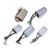
The Kelly KBS-X Brushless Motor Controller is a programmable device designed for efficient, smooth, and quiet control of electric motorcycles, golf carts, go-carts, and industrial motor speed or torque applications. It utilizes high-power MOSFETs and Pulse Width Modulation (PWM) to achieve efficiencies of up to 99%. A powerful microprocessor enables comprehensive and precise control, allowing users to adjust parameters, conduct tests, and obtain diagnostic information quickly and easily.
The controller manages BLDC motors, offering features such as extended fault detection and protection, LED flashing patterns for fault indication, and monitoring of battery voltage to prevent over-discharge. It supports motor drive power cutback when battery voltage drops below a preset level and completely cuts out at an even lower voltage. Built-in current loop and overcurrent protection are standard. The controller offers configurable motor temperature protection, cutting back current at low temperatures and protecting the battery at high temperatures. It also handles current cutback and shutdown at high temperatures. Regenerative braking is supported, with the controller recovering mechanical energy and charging the battery.
The controller provides a +5V output for various kinds of sensors, including Hall effect type, and supports 3 switch inputs that are activated by connection to ground for throttle, brake, and reversing. It has 3 analog 0-5V inputs that default to throttle input, brake input, and motor temperature input. A pulsed reverse alarm output is included. It features a main contactor driver that cuts off power if any fault is detected, and a current meter to display both drive and regen current. A configurable boost switch enables maximum output power. An economy switch limits the maximum current to half power. Maximum reverse power is configurable to half power. Enhanced regen brake function with a novel ABS technique provides powerful and smooth regen. Configurable 12V brake signal input, in lieu of motor temperature sensor, is available. An optional joystick throttle with a bi-symmetrical 0-5V signal for both forward and reverse is supported. The controller is configurable for motor over-temperature detection and protection with thermistors like KTY84-130. It also provides 3 Hall position sensor inputs and an optional 5V supply output.
The controller boasts intelligence with a powerful microprocessor, synchronous rectification, ultra-low drop, and fast PWM for very high efficiency. It includes electronic reversing and comprehensive voltage monitoring on 3 motor phases, bus, power supply, 12V, and 5V sources. Current sensing is performed on all 3 motor phases with a current control loop. Hardware overcurrent and overvoltage protection are integrated. Users can configure limits for motor current and battery current. It supports torque mode, speed mode, and balanced mode operation. The device has low Electromagnetic Compatibility (EMC) and provides LED fault codes for diagnostics. Battery protection features include current cutback, warning, and shutdown at configurable high and low battery voltages.
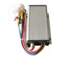
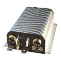
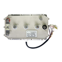
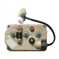
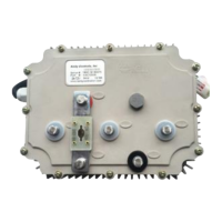
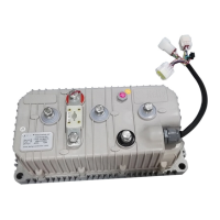
The rugged aluminum housing ensures maximum heat dissipation and durability in harsh environments. High-current terminals and aviation connectors are used for small signals. Thermal protection includes current cutback, warning, and shutdown at high temperatures. It is configurable for 60-degree or 120-degree Hall position sensors and supports motors with any number of poles. The controller supports three modes of regenerative braking: brake switch regen, release throttle regen, and 0-5V analog signal variable regen. A configurable high pedal protection feature prevents operation if high throttle is detected at power-on. Current multiplication allows the controller to draw less current from the battery while outputting more current to the motor. Installation is easy, supporting 3-wire potentiometers. Programming is done via a standard PC/Laptop computer with no special tools needed, and a user-friendly program is provided free of charge.
The controller's output mode can be set to Torque, Balanced, or Speed. Torque mode offers faster load response and good acceleration. Balanced mode provides fast response and a wide speed adjusting range. Speed mode ensures smooth operation and a wide speed adjusting range. It includes a "Start-up Delay Time" to stabilize B+ when powered on. The "Throttle Up/Down Rate" adjusts the pedal AD sampling frequency, affecting response time. "High Pedal Disable" and "Releasing Brake High Pedal Disable" functions detect current pedal status at power-up or when releasing the brake, reporting faults if effective throttle output is detected. "Motor Top Speed" and "Motor Top Speed In Reverse" can be limited. "Half Speed In Reverse" limits the maximum reverse speed to half of the maximum forward speed. "Boost Function" and "Economy Function" can be enabled or disabled to modify output current characteristics. An "ABS" function is available for enhanced braking.
Regeneration can be enabled, allowing the controller to recover mechanical energy and charge the battery. "Brake Switch Regen Mode" activates regen when the throttle is off and the brake switch is on. The "Max Allowed Regen Current" can be set for both releasing throttle regen mode and brake switch regen mode. The "Max Regen Current" defines the maximum regen current with the maximum signal from the brake sensor. "Brake Sensor Type" can be configured (Not Used, 3-wire resistive pot, Hall active throttle), and "Brake Sensor Starting Point" and "Ending Point" define the effective range of the brake sensor.
The controller contains no user-serviceable parts, and opening it will void the warranty. However, periodic exterior cleaning is recommended. Before any maintenance, power must be removed by disconnecting the battery, starting with the positive terminal. The capacitors in the controller should be discharged by connecting a load (e.g., contactor coil, resistor, or horn) across the B+ and B- terminals. Any dirt or corrosion should be removed from the bus bar area by wiping the controller with a moist rag, ensuring it is dry before reconnecting the battery. Connections to the bus bars must be tight, using two well-insulated wrenches to avoid physical stress.
Configuration of the controller can be done via an RS232 or USB port. During configuration, motor wiring should be disconnected, and B+ and throttle connections should be avoided. The controller may display fault codes during this process, but it will not affect programming. A straight-through RS232 cable or a USB converter provided by Kelly should be used to connect to a host computer. Power supply (>+18V for 24V controllers, >+8V for other controllers) must be provided to the PWR pin, and the supply negative connected to any RTN pin. The KBS-X user program is specifically for KBS-X controllers and requires the Kelly RS232 Converter for communication. The free configuration software can be downloaded from the Kelly Controls website.
The manual provides a detailed installation check list, emphasizing safety precautions such as placing the vehicle on blocks, ensuring no one stands in front of or behind the vehicle, turning off the PWR switch and brake, and using well-insulated tools. It guides users to verify correct wiring, check LED indicators for normal operation (Green LED steady, Red LED off), and troubleshoot fault codes if necessary. The motor should spin in the selected direction with increasing throttle, and if not, the LED code table should be consulted. Finally, the vehicle should be tested in a clear area for smooth acceleration and good power.
The LED codes are categorized into Green LED Codes (indicating normal operation or minor issues like software upgrades, low battery voltage, or damaged controller) and Red LED Codes (indicating various faults such as overvoltage, low voltage, over temperature, motor not starting, internal volts fault, over temperature, throttle error at power-up, frequent reset, internal reset, Hall throttle open/short-circuit, non-zero throttle on direction change, regen or start-up over-voltage, Hall sensor error, and motor over-temperature). The Red LED flashes once at power-on as a confidence check and then normally stays off. Flash codes are interpreted by the number of flashes, with a two-second pause between multiple flash code groups.
| Brand | Kelly |
|---|---|
| Model | KBS-X Series |
| Category | Controller |
| Language | English |