14
C2N Series Tankless Heater Installation
5/3/2016 Bradley • 215-1821 Rev. B; ECN 16-17-005
1
2
3
4
5
Special Installation and Operating Instructions
Tankless Water Heaters With Optional Class I Division 2 Purge EXP2 Option
General Information
All Keltech Tankless Water Heaters with a model number suffix of – EXP2 have been fitted with a Z purge system to
pressurize the enclosure suitable for use in Class I Division 2 Hazardous Locations.
A Continuous Flow (Model CF) Mini-Z Pressurizing System has been fitted to the bottom of the enclosure.
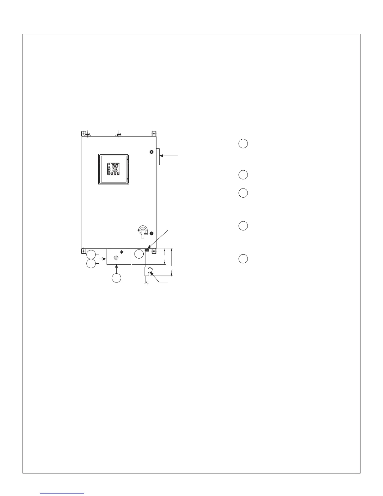
18" (458mm)Max
Explosion proof
sealing fitting
supplied by others
Purge System
Relief Valve
Conduit Hub
Class 1 Div. 2
supplied by others
1
1
2
3
4
5
2
4
5
Suggested region for power
entrance at left/bottom of enclosure.
Entrance hole and components to
be provided by installer.
Purge Control Panel
Class 1 Division 2
All installation egress from
panel must be sealed (electrical
conduit) for proper explosion proof
installation.
Spark arrestor with calibration orifice
is located behind the purge control
unit and through the bottom of the
enclosure.
Purge gas/compressed air inlet
fitting here.
EXP2 Installation Notes
1. Any tubing, conduit or fittings connected to the Pressurized Enclosure (PE) must conform to local codes for
flammability ratings.
2. All egress into PE must be plugged and properly sealed to minimize leakage of purge air. Use hazardous
location sealing fittings suitable for Class I locations within 18" (458mm) of enclosure.
3. The EXP2 purge system option is a continuous flow purge system and is calibrated to flow at 0.9 SCFM
(1.5291 CMH). To minimize waste, plug and seal all openings and conduit.
4. The system is designed for use primarily with compressed air. The source of the compressed air must be
from a non-classified area (see Purge Gas Supply Notes). Purge air must be clean, dry and free of flammable
gases. When inert compressed gases are used (Nitrogen, for example) the installer and facility manager must
take suitable precautions on-site so that buildup of the inert gas does not present a health hazard. Where risk
of asphyxiation exists, a warning label must be fitted to the Pressurized Enclosure (PE).
5. Adjustment of Purge System is not necessary. System is fully calibrated.
6. Connect to Purge System where indicated. Connection port is 1/4" NPT female. Supply pressure must be
regulated to 60–115 PSI (4-8 bar).
5"
(127mm)