A20
DR K01 K30
S16 NT
1
2
3
4 5
6 7 9 10 11 12
L
N
~
HP
S10
M
l
~
M10
HP
S11
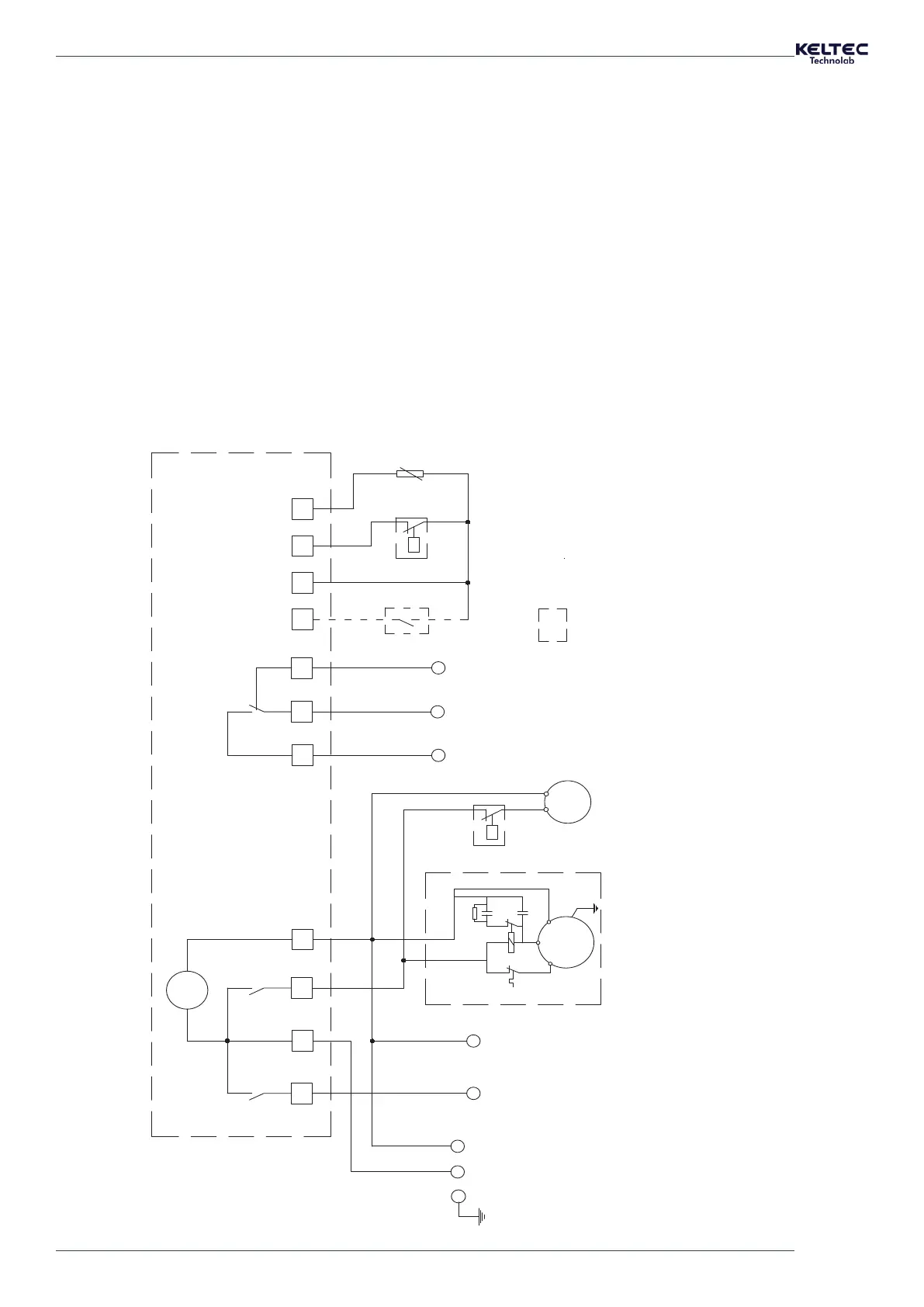
ELECTRICAL SUPPLY LINE
SINGLE PHASE + PROTECTION EARTH
CABLES SIZE
ELECTRICAL
SPECIFICATIONS
MKP-300 RLA 5,1A 0,996kW
MKP-396 RLA 5,1A 1,033kW
MKP-498 RLA 5,8A 1,082kW
COMPRESSOR
UN 230V/1~/50Hz
FAN MOTOR
UN 230V/1~/50Hz
MKP-300 RLA 0,7A 0,095kW
MKP-396 RLA 0,7A 0,095kW
MKP-498 RLA 0,7A 0,095kW
S01 MAIN PROTECTION AND DISCONNECTING MEANS
SHALL BE PROVIDED BY THE INSTALLER OF RESIDUAL
CURRENT AUTOMATIC CIRCUIT BREAKER
FIELD INSTALLED
MAXIMUM SET: %15
MKP-300
MKP-396
MKP-498
3x1,5mm2
3x1,5mm2
3x1,5mm2
EV3: Controller
SP: Power supply
AL: Alarm contact
A20: Drain supply
DR: Drain valve relay
A31: Bleeder resistor
A40-1:Start capacitor
A40-2: Run capacitor
K01: Compressor start relay
K02: Compressor motor contactor
K30: Alarm relay
S10: Fan pressure switch
S11: High pressure switch
S16: Filter service contact (optional)
M01: Compressor motor
M10: Fan motor
P: Compressor motor overload protector
NT: Temperature sensor (NTC)
HP indicates high pressure
M01
M
l
~
A/S
C/C
P/R
K01
A31
P
A40-2
A40-1
1
4
1
4
3
4
2
4
16
4
4
4
3
10
10
10
12
11
SP
EV3
5
6
7
AL
PE
 Loading...