Kelvinator Gas Continuous Flow hot water system for the plumber 5
For the plumber
PLEASE NOTE this water heater is supplied factory set to
comply with the requirements of AS 3498.
If you are installing a 60°C or 70°C gas continuous ow hot
water system, a tempering valve is to be installed for the
hot water supplying sanitary fixtures primarily used for the
purpose of personal hygiene.
Please follow all the installation instructions in this manual
including the following instructions regarding the water
heater outlet connection:
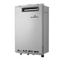
1. When connecting the hot water supply to the xtures in
the property, a minimum of three (3) metres of pipework
must be used between the outlet of the water heater and
the rst tap or outlet. If you are installing a 60°C or 70°C
model, only a minimum of one (1) meter of pipework is
necessary. See diagram to the right.
2. The hot water outlet line from the water heater should be
covered with 20mm pipe insulation or similar to prevent
heat loss and persons coming in contact with it.
3. When the installation is completed, the temperature of
the hot water supplying sanitary fixtures primarily used
for the purpose of personal hygiene, for example the
bathroom shower/taps, shall be checked to ensure it does
not exceed 50°C. If a 50°C model gas continuous ow hot
water system has been installed, all hot water taps and
fixtures need to be checked to ensure they do not
exceed 50°C.
MODELS
KGC20BNA
KGC20KNA
KGC20SNA
KGC20BLA
KGC20KLA
KGC20SLA
KGC26BNA
KGC26KNA
KGC26SNA
KGC26BLA
KGC26KLA
KGC26SLA
Capacity L/min 20L/min 26L/min
Gas Input MJ/h 160 195
Supply Inlet Pressure
kPa – Nat. Gas
1.13 min. 1.13 min.
2.75 max. 2.75 max.
Supply Inlet Pressure
kPa - LPG
2.61 min 2.61 min
2.89 max 2.89 max
Water Supply
Pressure kPa
150* min 150* min.
1200 max 1200 max
Height mm 542 542
Depth mm 170 215
Width mm 350 350
Weight kg 15.7 17. 2
Gas Connection mm 20 BSP 20 BSP
Water Connections 15 BSP 15 BSP
Ignition Electronic Electronic
Electrical Supply Voltage 240 AC 240 AC
Operating current 0.8A 0.8A
*The water heater will operate at reduced performance if inlet water supply
pressure is below 340 kPa.
Note: If the gas supply pressure exceeds the maximum
value in the above table for the respective gas type, fit an
appropriate pressure limiting valve at the inlet to the gas inlet
of the water heater.
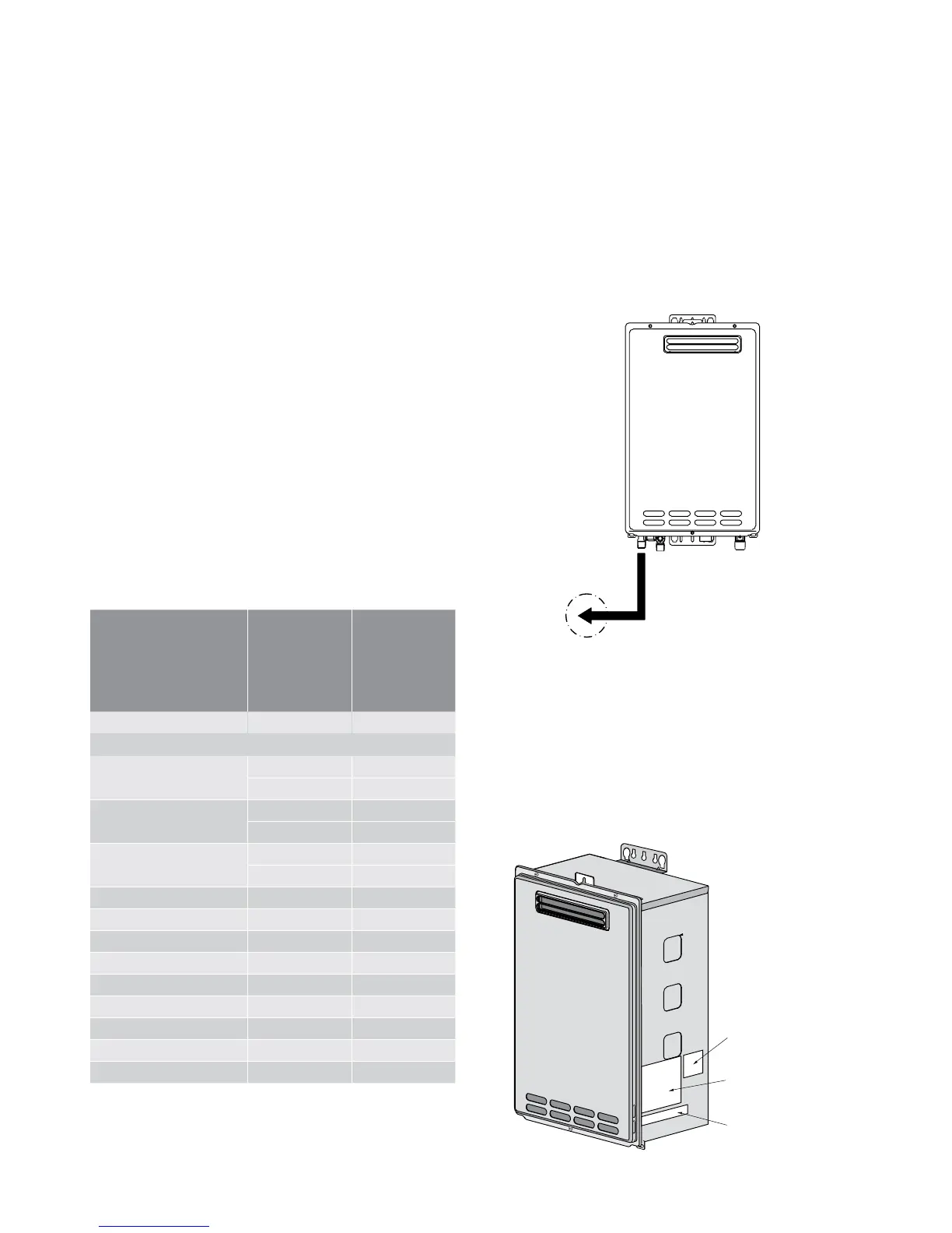
• For information relating to burner test point pressures
and injector sizes refer to the rating plate located on the
right hand side of the cabinet for each model (please
refer to the diagram at the bottom of this page showing
the locations of the labels on the water heater).
• For information relating to overall dimensions and
connection points refer to diagrams on pages 6 & 7.
• Before installing in areas over 1500 m above sea level,
contact the manufacturer for instructions.
• Total length to rst tap or outlet is required to be a
minimum of 3 metres from the outlet connection of
the water heater (minimum 1 metre for 60°C and 70°C
models).
• Pipe size is nominal 1/2" from hot water outlet to the rst
tap or outlet.
Accessories
4 tapping screws are included with the water heater.
Rating label
position
Serial number
label position
Gas type label
position
 Loading...